11- 11 -
HWE10170 GB
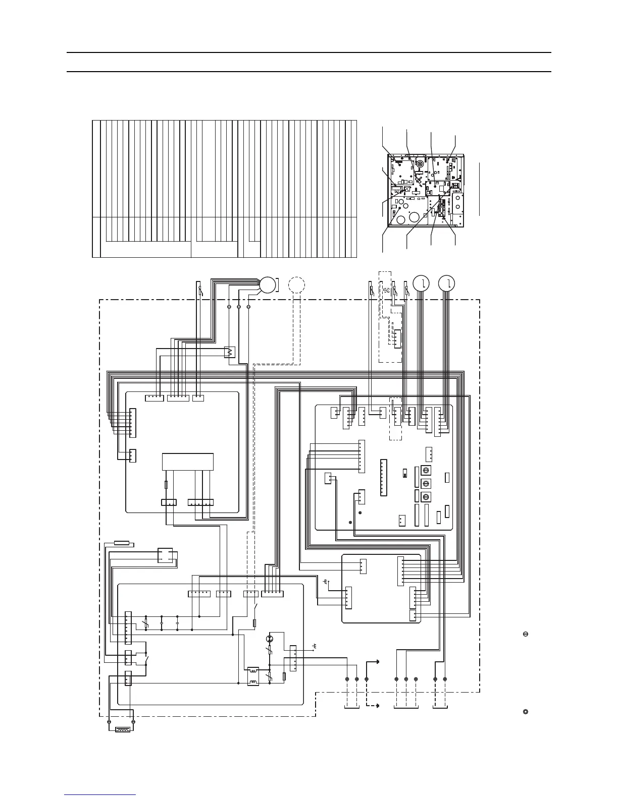
[6] Wiring Diagram
0
1
2
3
4
5
6
7
8
9
0
1
2
3
4
5
6
7
8
9
0
F
E
D
C
B
A
9
8
7
6
5
4
3
2
1
6
4
2
1
3
1
2
2
2
1
1
25431
21
85431
21
31
442331
4321
6
6
5
5
5
4
4
3
3
3
2
2
1
1
1
54321
1
2
3
4
5
1
2
76543213
3
1
1
1
2
3
4
5
3
3
1
1
1
3
8
7
1
6
6
5
3
43
5
3
2
1
1
3
3
1
1
CN25
F01
IPM
(BLUE)
CNCT2
CNFAN
CNP
X010
X100
CNR1
(RED)
(RED)
CNACL
ZNR
003
C015
C016
ZNR
002
DSA
001
ZNR
001
F001
F100
CNPW1
CNRSC
CNRSP
CNXC1
CNXB1
CNDB
CNPW2
CN18V
(GREEN)
CNTH
(RED)
CNCT1
CNRS2
CN15V
CNVDC
CNDP
CNINV
NF
CNXC2
CN100
CN41
CN90
LED2
LED1
CN3A
(BLUE)
CN2M
(BLUE)
CN7V
CN60
CN44
CN4F CN4F
CN20
(RED)
CN32
SW3
SWC
SW5
SWA
SWE
ONOFF
SW2SW1
SW4
SW11SW12SW14
1s
DIGIT DIGIT
( ) ( ) ( )
10ths
BRANCH
No.
CNXB2
POWER SUPPLY
AC208-230V
60Hz
Note 1
Note 1
ACL
2
2
1
1
INSIDE SECTION OF CONTROL BOX
TO MA REMOTE
CONTROLLER
TO OUTDOOR UNIT
BC CONTROLLER
REMOTE CONTROLLER
MF
DP
MS
3
~
M
1
~
UVW
R
NF.B.
INV.B.
I.B.
P. B .
TB2
DB01
ACCT
TB5
TB15
LEV1
LEV2
THHS
TH21
TH22
FS
TH23
L1
3
4
2
1
3
3
1
1
2
2
M1
M2
S(SHIELD)
L2
G
1
2
DB01 RNF.B.
TB2
TB5
TB15
P. B.
I.B.
ACCT
INV.B.
PARTS LOCATION
Inside < > is the optional parts.
NOTE:1.The part of thin dotted line indicates the circuit for optional parts.
2.To perform a drainage test for the drain pump turn on the SWE
on the control board while the indoor unit is being powerd.
*Be sure to turn off the SWE after completing a drainage test or test run.
3.The wirings to TB2,TB5,TB15 shown in dotted line are field work.
4.Mark indicates terminal block, connector.
5.Use copper supply wire.
SYMBOL NAME
SYMBOL EXPLANATION
Aux. relay
X010,X100
Varistor
Arrester
Intelligent power module
Fuse(AC250V 15A)
DSA001
IPM
F01
Electronic linear expan.valve
LEV1,LEV2
F001
F100
NF
Fuse(AC250V 10A)
Fuse(3.15A)
Noise filter
Switch (for mode selection)
Switch (for capacity code)
Switch (for mode selection)
Switch (for model selection)
Switch (for mode selection)
Switch (1s digit address set)
Switch (10ths digit address set)
Switch (BRANCH No.)
Switch (for static pressure selection)
Switch (for static pressure selection)
TB2
TB5
TB15
CN25
I.B.
NF.B.
INV.B.
P. B .
TH21
TH22
TH23
THHS
<FS>
Connector
Indoor controller board
Noise filter board
Inverter board
Power supply board
Power source terminal block
Transmission terminal block
Transmission terminal block
Float switch
Thermistor(piping temp.detection/liquid)
Thermistor(piping temp.detection/gas)
Thermistor(heatsink)
Thermistor(inlet air temp.detection)
MF
Fan motor
AC reactor (Power factor improvement)
Resistor
Diode bridge
LED (Power supply)
Current Sensor (AC)
LED (Remote controller supply)
ACL
R
DB01
LED1
ACCT
LED2
Connector (emergency operation)
Connector (Remote switch)
CN32
Connector (HA terminal-A)
CN41
Connector (Wireless)
CN90
SW1
SW2
SW3
SW4
SW5
SW11
SW12
SW14
SWA
SWC
SWE
ZNR01~
ZNR03
Drain pump
<DP>
t°
t°
t°
t°
U
UU
M
M
PEFY-P72,96NMHSU-E
HWE10170.book 11 ページ 2011年7月19日 火曜日 午後2時57分
 Loading...