3 System Configuration
3.4 Connection with PLC
20
FX3U-64CCL User's Manual
3.4 Connection with PLC
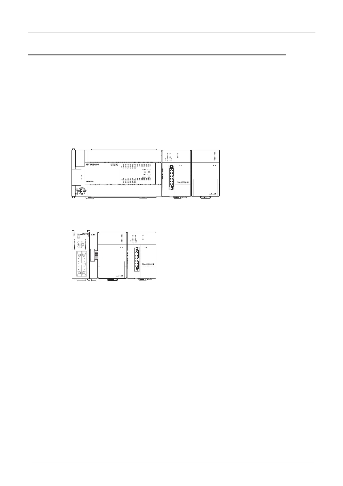
The 64CCL connects with an FX3U PLC via an extension cable.
The 64CCL is handled as a special extension block of the PLC. The unit number of the 64CCL is
automatically assigned No.0 to No.7 (Unit No.1 to No.7 is assigned when the main unit is an FX
3UC-32MT-
LT(-2).) starting from the special function unit/block closest to the PLC main unit. (This unit number is used for
the designation of a FROM/TO instruction.)
For details on the assignment of the I/O number and unit number of the PLC, refer to the following manual
corresponding to the connected PLC.
→ FX
3G Hardware Edition
→ FX
3U Hardware Edition
→ FX
3UC Hardware Edition
• Only one 64CCL unit can be connected to the FX
3G/FX3U/FX3UC PLC.
•An FX
2NC-CNV-IF or FX3UC-1PS-5V is necessary to connect the 64CCL with the FX3UC PLC.
• The optional FX
0N-65EC (FX0N-30EC) and FX2N-CNV-BC are necessary to lengthen the extension cable.
• The number of I/O points occupied by the 64CCL is eight. Make sure that the total number of I/O points
(occupied I/O points) of the main unit, power extension unit(s) extension block(s) and the number of points
occupied by special function blocks does not exceed the maximum number of I/O points of the PLC.
For information on the maximum number of I/O points of the PLC, refer to the respective product manual.
→ FX
3G Hardware Edition
→ FX
3U Hardware Edition
→ FX
3UC Hardware Edition
FX
3U
-64CCL
POWER
RUN
ERR.
RUN
ERR.
SD
RD
L
L
POWER
MOTOR-Y
START
DOG
INT0
INT1
A
B
X-RE ADY
Y-R EADY
X-ERR OR
Y-E RROR
START
DOG
INT0
INT1
A
B
MOTOR-X
POWER
MOTOR-Y
START
DOG
INT0
INT1
A
B
X-RE ADY
Y-R EADY
X-ERR OR
Y-E RROR
START
DOG
INT0
INT1
A
B
MOTOR-X
FX
3U
-64CCL
POWER
RUN
ERR.
RUN
ERR.
SD
RD
L
L
Other
extension
units/blocks
Other
extension
units/blocks
FX3G/FX3U PLC FX3U-64CCL
FX
3UC PLC
FX
3U-64CCL
FX
2NC-CNV-IF

 Loading...


