4 Installation
4.2 Direct mounting
23
FX3U-64CCL User's Manual
1
Introduction
2
Specification
and function
3
System
Configuration
4
Installation
5
Wiring, Start-up
procedure
6
FX
3U
-64CCL
setting (switch
setting)
7
Buffer Memory
8
Program
Example
9
Troubleshooting
A
Version
Information
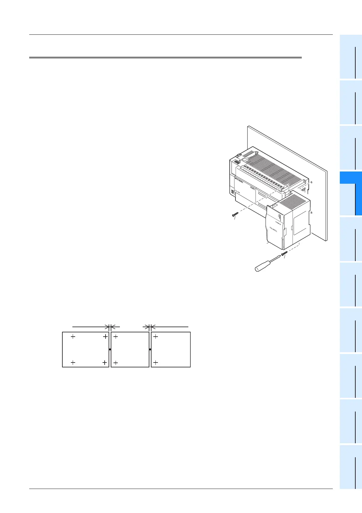
4.2 Direct mounting
The product can be installed directly with screws.
An interval space of 1 to 2 mm (0.04" to 0.08") between each unit is necessary.
For installation details, refer to the following respective PLC manual.
→ For mounting hole pitches, refer to Section 1.2.
→ Refer to the FX
3G Hardware Edition
→ Refer to the FX
3U Hardware Edition
→ Refer to the FX
3UC Hardware Edition
1 Create mounting holes in the mounting sur-
face according to the external dimensions
diagram.
2 Fit the 64CCL (A in the figure to the right) to
the mounting holes and tighten with M4
screws (B in the figure to the right).
For the screw position and quantity, refer to the dimen-
sioned drawing specified below.
→ For dimensions, refer to Section 1.2.
3 Connect the extension cable.
Connect the extension cable to the main unit, I/O exten-
sion unit/block or special function unit/block on the left side
of the product.
(Refer to Step 3 in Section 4.1.)
For information on the extension cable connection proce-
dure, refer to the respective PLC manual.
→ Refer to the FX3G Hardware Edition
→ Refer to the FX
3U Hardware Edition
→ Refer to the FX
3UC Hardware Edition
• Example of anchoring
FX
3U
-48M
FX
3U
RUN
POWER
ERROR
B
A
T
T
FX
3U
ERROR
RUN
B
A
T
T
POWER
0
3
1
2
IN
OU
T
6
4
5
21
7
20
24
22
23
26
25
10
1
1
13
12
16
14
15
17
27
0
3
1
2
6
4
5
21
7
20
2422
23
26
25
10
1
113
12
16
14
15
17
27
B
B
A
FX
3G
/FX
3U
Series
main unit
(+ shows the M4 screw)
other extension
equipment
1 to 2mm
(0.04" to 0.08")
1 to 2mm
(0.04" to 0.08")
FX
3U
-64CCL

 Loading...


