58
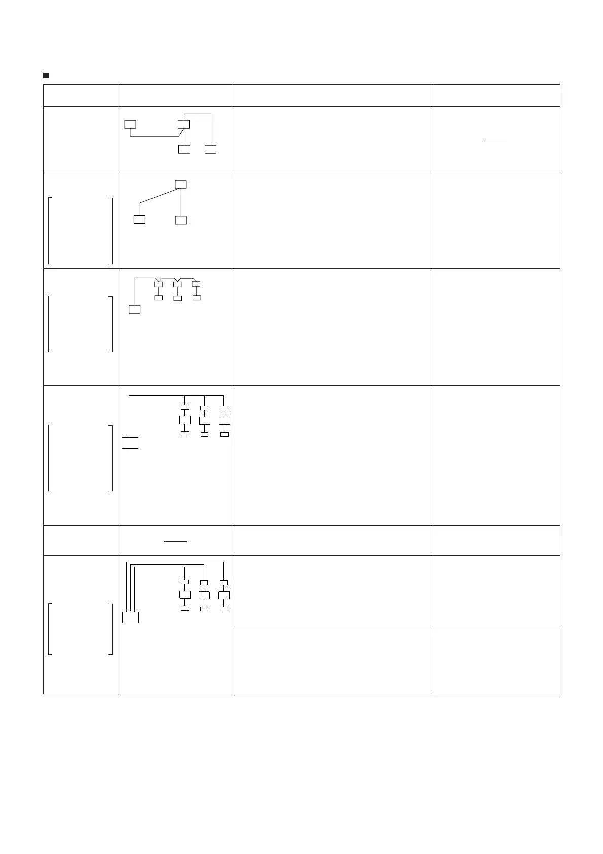
System Name System Diagram Features
Parts Required in Addition to Standard System
Components (Indoor/Outdoor Units, Remote Controller)
Indoor unit
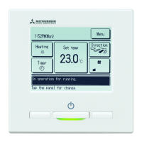
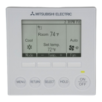
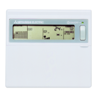
Remote
Controller
Outdoor
unit
A.Remote control-
ler operation
(Standard)
B.Remote control-
ler operation
Use of two con-
trollers enables
operation of the air
conditioner both
from a distance
and nearby.
C.Group control
operation
Use of one remote
controller to con-
trol multiple air
conditioners with
the same settings
simultaneously.
* Outdoor unit`s re-
frigerant address
needs to be set.
D.
Remote/local
combined control
operation
Allows start/stop
of the air condi-
tioner from a dis-
tance, and prohib-
its/permits start/
stop from remote
controllers.
E.Operation by
external signal
F.Control by
external signal
and remote
display
Enables you to
display the op-
eration state and
control start/stop
from a distance.
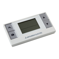
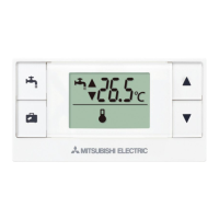
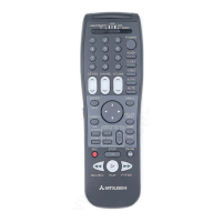
There are two types of remote controllers: wired type
and wireless type.
Simultaneous twin units are counted as one unit, and
the indoor units are started or stopped
simultaneously.
Up to two remote controllers can be connected to
one group.
Simultaneous twin units are counted as one unit.
Operation control by the latest command (last en-
tered priority)
Wired and wireless remote controllers can be com-
bined as a pair.
One group can consist of up to 16 indoor units, and
they can be started sequentially by connecting the
remote controller to them and assigning an address
to each outdoor unit.
Simultaneous twin units are counted as one unit.
All the units belonging to the same group are oper-
ated in the same mode, but thermostats can be
turned ON/OFF individually for each outdoor unit.
Up to two remote controllers can be connected.
All the air conditioners can be turned ON/OFF collectively
from a distance.
Operation can be switched between the remote operat-
ing panel and local controller.
Operations (e.g., temperature adjustment, airflow, air-
flow direction) except for start/stop operations can be
performed even if the operations from the local remote
controllers are prohibits.
In the case of simultaneous twin units, connect the
controller to one indoor unit only. If connected to
two or more indoor units, an error (operation stop)
may occur.
Control by an external timer is possible by connecting it.
Use of optional "remote ON/OFF adapter" enables
remote control via relay. (Level signal)
Extraction of non-voltage contact output
Use of optional "remote operation adapter" and
"remote display panel" (Part to be provided at
your site) provides non-voltage contact outputs of
signals (operation, error) and operation/stop input
function.
Extraction of DC12 V contact output
Use of optional "Multiple remote controller adapter"
and "remote display panel"
(Part to be provided at
your site)
provides DC12 V contact outputs of signals
(operation, error)
and operation/stop input function.
Indoor
unit
Remote
Controller
* One of the wired remote con-
trollers must be set as a sub
remote controller.
Outdoor
unit
Indoor
unit
Remote
Controller
Indoor unit
Remote Controller
Relay box
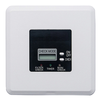
Remote operating panel
Adapter
Remote display panel
(operation, error)
Indoor unit
Remote Controller
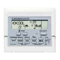
Wired remote controller (addi-
tional)
(PAR-21MAA)
Remote ON/OFF adapter
(PAC-SE55RA-E)
Relay box
(Part to be provided at your site)
Remote operating panel
(Part to be provided at your site)
Remote ON/OFF adapter
(PAC-SE55RA-E)
Remote operation adapter
(PAC-SF40RM-E)
Remote display panel
(Part to be provided at your site)
Multiple remote controller adapter
(PAC-SA88HA)
Remote display panel
(Part to be provided at your site)
X. System Control (for Mr. SLIM)
VARIETY OF SYSTEM FUNCTION
 Loading...