C
Cameron AdkinsAug 22, 2025
Why does my Mitsubishi Amplifier show an overvoltage error?
- JJustin VazquezAug 22, 2025
An overvoltage error in your Mitsubishi Amplifier is due to a main circuit voltage error.
Why does my Mitsubishi Amplifier show an overvoltage error?
An overvoltage error in your Mitsubishi Amplifier is due to a main circuit voltage error.
What causes an overspeed error on a Mitsubishi MR-J4-40A Amplifier?
An overspeed error on your Mitsubishi Amplifier is caused by abnormal motor speed.
What causes a main circuit error in my Mitsubishi Amplifier?
A main circuit error in your Mitsubishi Amplifier can occur due to: * A ground fault detected by the hardware detection circuit. * A ground fault detected by the software detection function.
Why is my Mitsubishi Amplifier showing a servo motor overheat error?
A servo motor overheat error in your Mitsubishi Amplifier can be due to: * Abnormal temperature of servo motor 1. * Abnormal temperature of servo motor 2. * Thermistor disconnected error. * Abnormal temperature of servo motor 3. * Abnormal temperature of servo motor 4.
What causes undervoltage on Mitsubishi Amplifier?
Undervoltage in your Mitsubishi Amplifier can be due to: * Voltage drop in the control circuit power. * Voltage drop in the main circuit power.
What does parameter error mean on my Mitsubishi MR-J4-40A Amplifier?
A parameter error on your Mitsubishi Amplifier indicates either a parameter setting range error or a parameter combination error.
What causes a regenerative error in my Mitsubishi Amplifier?
A regenerative error in your Mitsubishi Amplifier can stem from: * Regeneration heat error. * Regeneration signal error. * Regeneration feedback signal error.
What does a board error on my Mitsubishi Amplifier mean?
A board error on your Mitsubishi Amplifier indicates: * Board error 1. * Board error 2. * Board error 3.
What causes a servo control error on my Mitsubishi Amplifier?
A servo control error on your Mitsubishi Amplifier (specifically for linear servo motors and direct drive motors) can be caused by: * Servo control error by position deviation. * Servo control error by speed deviation. * Servo control error by torque/thrust deviation. * Fully closed loop control error by position deviation. * Fully closed loop control error by speed deviation. * Fully closed loop control error by position deviation during command stop.
What does encoder normal communication error 2 mean on Mitsubishi MR-J4-40A Amplifier?
Encoder normal communication error 2 on your Mitsubishi Amplifier can be caused by: * Encoder data error 1. * Encoder data update error. * Encoder data waveform error. * Encoder non-signal error. * Encoder hardware error 1. * Encoder hardware error 2. * Encoder data error 2.
| Series | MR-J4 |
|---|---|
| Type | AC Servo Amplifier |
| Rated Output | 0.4 kW |
| Rated Output Current | 2.0 A |
| Position Control | Yes |
| Communication | SSCNET III/H |
| Dynamic Brake | Built-in |
| Voltage Class | 200 V |
| Protection Functions | Overcurrent, Overvoltage, Overload, Overheat, Encoder Error, Regenerative Overload |
| Compatible Motor Series | HC-SF |
| Input Voltage | 200-230 VAC, ±10%, 50/60 Hz |
| Power Supply Voltage | 200-230 VAC, ±10%, 50/60 Hz |
Instructions to prevent electric shock, including power off procedures, grounding, and terminal insulation.
Instructions to prevent fire, including material selection for installation and circuit protection.
Instructions for correct and secure wiring of servo amplifiers and motors to prevent unexpected operation or injury.
Overview of MELSERVO-J4 series features, performance improvements over J3 series, and applicable fields.
Detailed specifications for 200 V and 400 V class servo amplifiers, covering ratings, input, control, protective functions, and safety performance.
Guidelines for installing servo amplifiers, including direction, clearances, and mounting hole details.
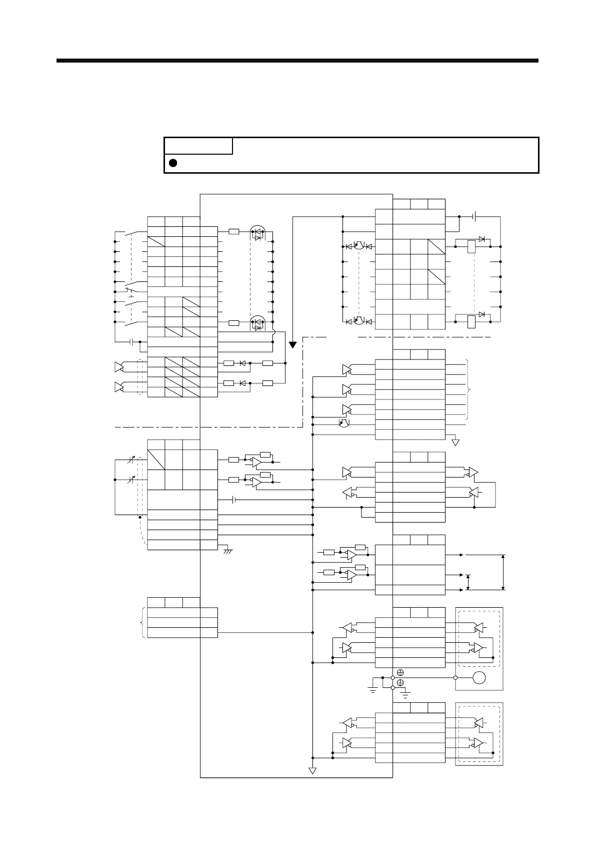
Detailed explanation of input power supply circuits for 200 V and 400 V class servo amplifiers.
Examples of I/O signal connections for position, speed, and torque control modes (sink and source interfaces).
Explanation of the forced stop deceleration function (SS1), including connection diagrams and timing charts.
Step-by-step procedure for initial startup, including wiring checks, parameter settings, and test operations.
Specific startup procedures for position control mode, including power on/off, stopping, test operations, and parameter settings.
Specific startup procedures for speed control mode, including power on/off, stopping, test operations, and parameter settings.
Specific startup procedures for torque control mode, including power on/off, stopping, test operations, and parameter settings.
List and description of basic setting parameters (PA01 to PA32) for operation and control modes.
List and description of gain and filter setting parameters (PB01 to PB64) for various control modes.
List and description of extension setting parameters (PC01 to PC80) for various control modes.
Parameters for setting linear servo motor and DD motor functions, including magnetic pole detection and resolution.
Explanation of gain adjustment modes: Auto tuning mode 1, Auto tuning mode 2, Manual mode, and 2 gain adjustment modes.
Procedure for executing one-touch tuning using MR Configurator2 or push buttons, and list of automatically set parameters.
Explanation of auto tuning function, including conditions for proper execution and parameters adjusted in different modes.
Overview of available filters: Low-pass, Machine resonance suppression, Shaft resonance suppression, and Robust filters.
Explanation of machine resonance suppression filters (notch filters) and their application in suppressing mechanical system resonance.
Function and parameter settings for Adaptive filter II, which detects and suppresses machine vibration automatically.
Function and parameter settings for Advanced vibration suppression control II, used to suppress load-side vibration.
Comprehensive list of alarms, their detail numbers, names, stop methods, and deactivation procedures.
Information on brake unit selection, connection examples, and parameter settings.
Information on external dynamic brakes, including selection, connection examples, and timing charts.
Specifications and mounting procedures for MR-BAT6V1SET and MR-BAT6V1BJ batteries used for absolute position detection.
Overview of the STO function, its compliance with safety standards, and its purpose.
Basic safety notes for installation, emphasizing qualified personnel and compliance with local regulations.
Connection examples for STO function using safety logic unit (MR-J3-D05) and external safety relay.
Safety precautions and wiring guidelines for direct drive motors, including connection diagrams.
Overview of fully closed loop system functions and configuration, including function block diagrams.
Explanation of error detection functions for fully closed loop control, including speed and position deviation.


