12. ABSOLUTE POSITION DETECTION SYSTEM
12 - 2
12.1.2 Restrictions
The system cannot be configured under the following conditions. Additionally, test operation cannot be
performed in the absolute position detection system. To perform test operation, select incremental system in
[Pr. PA03].
(1) Speed control mode and torque control mode
(2) Control switch-over mode (position/speed, speed/torque, and torque/position)
(3) Stroke-less coordinate system, e.g. rotary shaft, infinitely long positioning
(4) Changing electronic gear after home position setting.
(5) Using alarm code output.
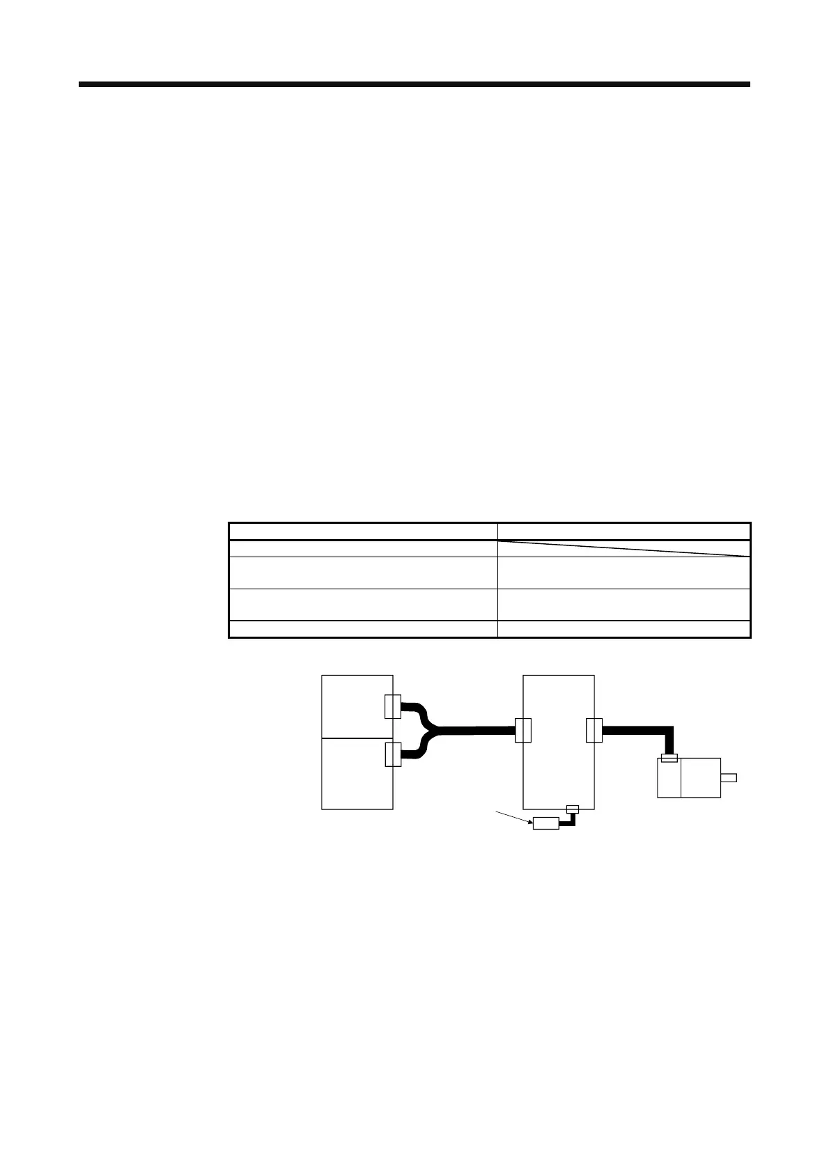
12.1.3 Structure
The following shows a configuration of the absolute position detection system. For the battery connection,
refer to (2) (b) of section 12.2.1 for the MR-BAT6V1SET battery. For the battery connection, refer to (2) (b) of
section 12.2.2 for the MR-BAT6V1BJ battery for junction battery cable.
Positioning module I/O module
QD70P_, QD70D_
QD75P_N, QD75D_N
QX40, QX41, QX42
QY40, QY41, QY42, QY50
LD75P4, LD75D4
LY40NT5P, LY41NT1P, LY42NT1P
LY40PT5P, LY41PT1P, LY42PT1P
FX
2N
-_GM, FX
2N
-_PG FX
2N
series, FX
0N
series
Servo motor
QD75D_N
etc.
Programmable controller Servo amplifier
CN1 CN2
Battery
I/O
CN4
 Loading...

