11. OPTIONS AND AUXILIARY EQUIPMENT
11 - 41
11.5 FR-CV-(H) power regeneration common converter
POINT
For details of the power regeneration common converter FR-CV-(H), refer to the
FR-CV Installation Guide (IB(NA)0600075).
Do not supply power to the main circuit power supply terminals (L1, L2, and L3)
of the servo amplifier. Doing so will fail the servo amplifier and FR-CV-(H).
Connect the DC power supply between the FR-CV-(H) and servo amplifier with
correct polarity. Connection with incorrect polarity will fail the FR-CV-(H) and
servo amplifier.
Two or more FR-CV-(H)'s cannot be installed to improve regeneration capability.
Two or more FR-CV-(H)'s cannot be connected to the same DC power supply
line.
When using FR-CV-(H), set [Pr. PA04] to "0 0 _ _" to enable EM1 (Forced stop
1).
When using the FR-CV-(H) power regeneration common converter, set [Pr. PA02] to "_ _ 0 1" and set [Pr.
PC27] to "_ _ _ 1".
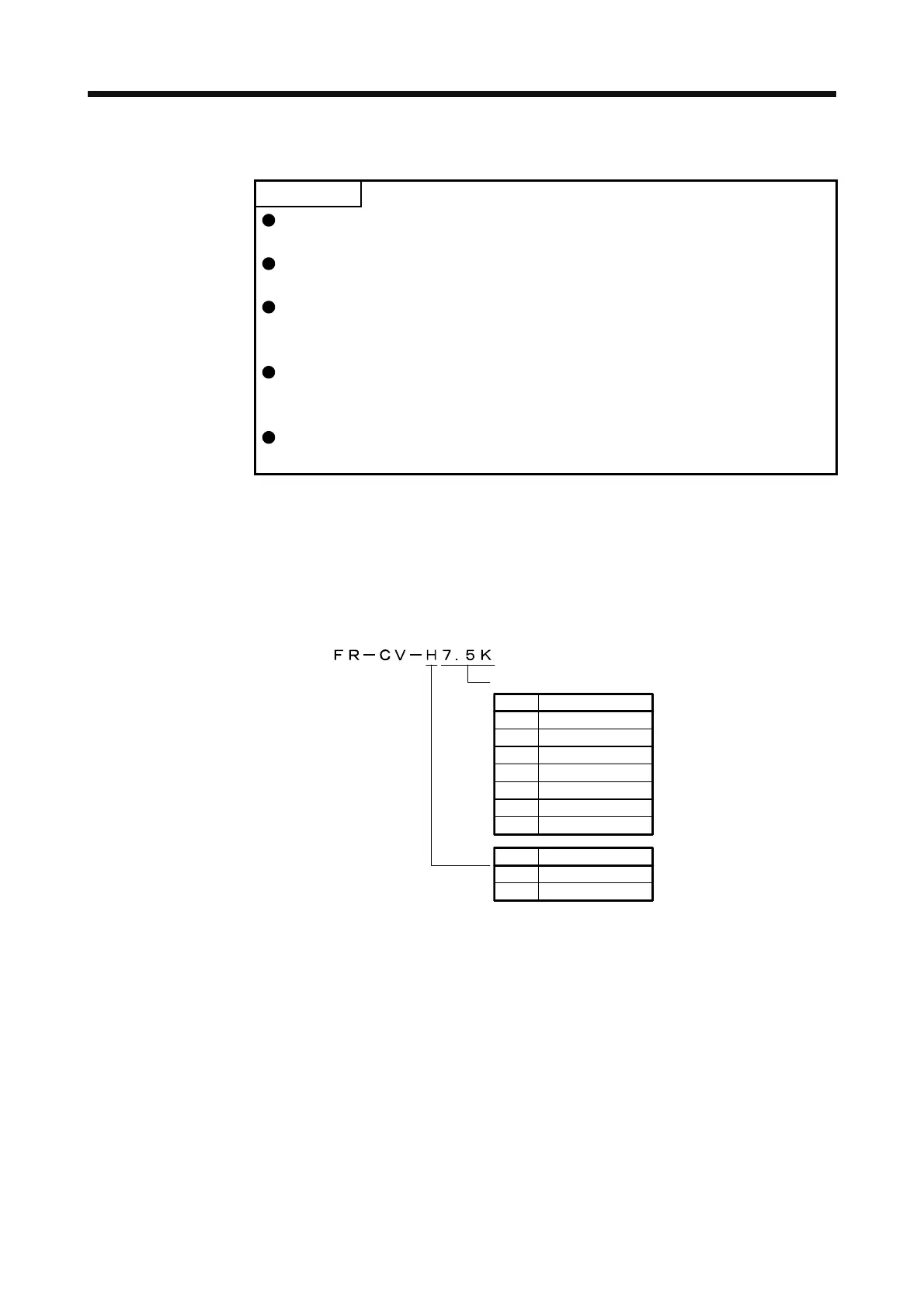
11.5.1 Model designation
The following describes what each block of a model name indicates. Not all combinations of the symbols are
available.
Capacity
Symbol Capacity [kW]
22K 22
30K 30
37K 37
55K 55
Symbol Voltage class
H 400 V class
7.5K 7.5
11K 11
15K 15
None 200 V class
 Loading...

