1. FUNCTIONS AND CONFIGURATION
1 - 31
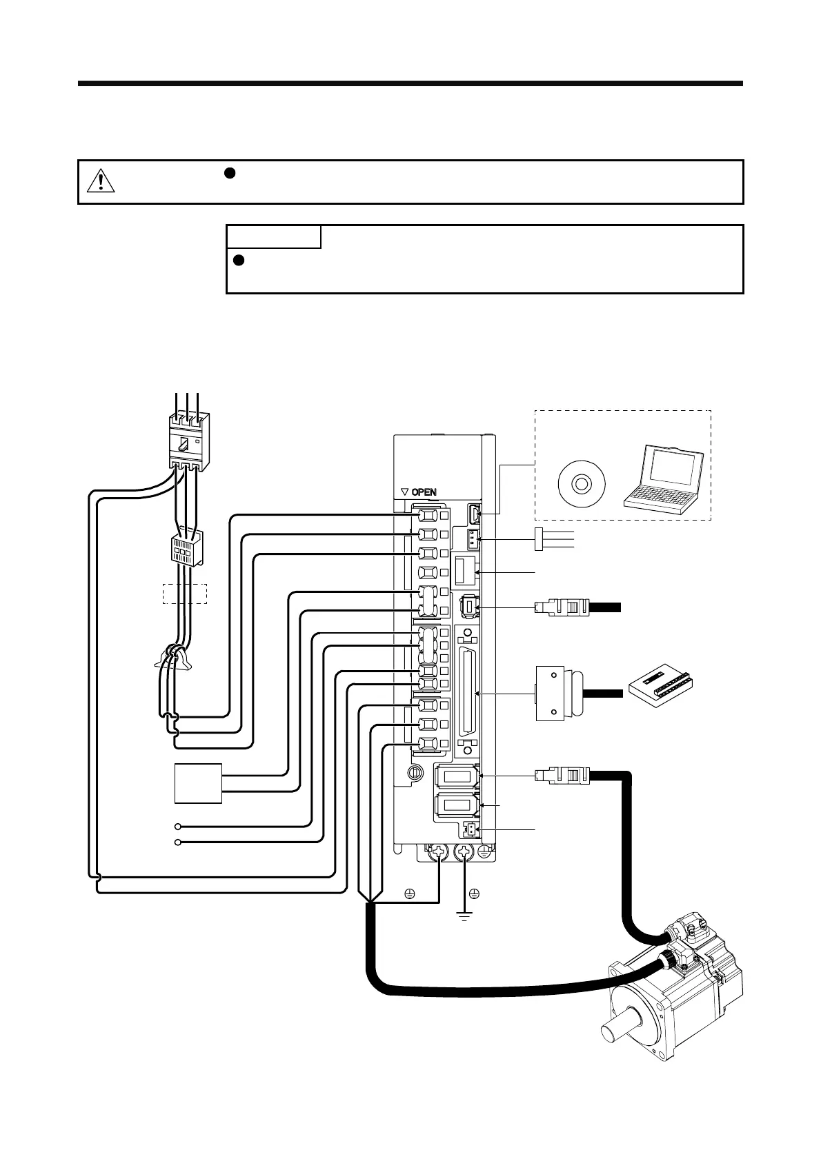
1.8 Configuration including peripheral equipment
CAUTION
Connecting a servo motor of the wrong axis to U, V, W, or CN2 of the servo
amplifier may cause a malfunction.
POINT
Equipment other than the servo amplifier and servo motor are optional or
recommended products.
(1) 200 V class
(a) MR-J4-200A(-RJ) or less
The diagram shows MR-J4-20A-RJ.
CN4
CN5
P+
C
L11
L21
P3
P4
MR Configurator2
CN3
CN6
CN8
CN1
CN2
W
V
U
L1
L2
L3
RS T
CN2L (Note 4)
Line noise
filter
(FR-BSF01)
Regenerative
option
Servo motor
Personal
computer
(Note 3)
Magnetic
contactor
(MC)
Power factor
improving DC
reactor
(FR-HEL)
Molded-case
circuit breaker
(MCCB)
To safety relay or
MR-J3-D05 safety
logic unit
Junction terminal block
(Note 2)
Power
supply
Battery
Personal computer and other
(Note 1)
Analog monitor
 Loading...

