1 - 3 1 - 3
MELSEC-Q
1 GENERAL DESCRIPTION
1.1 SFC Program
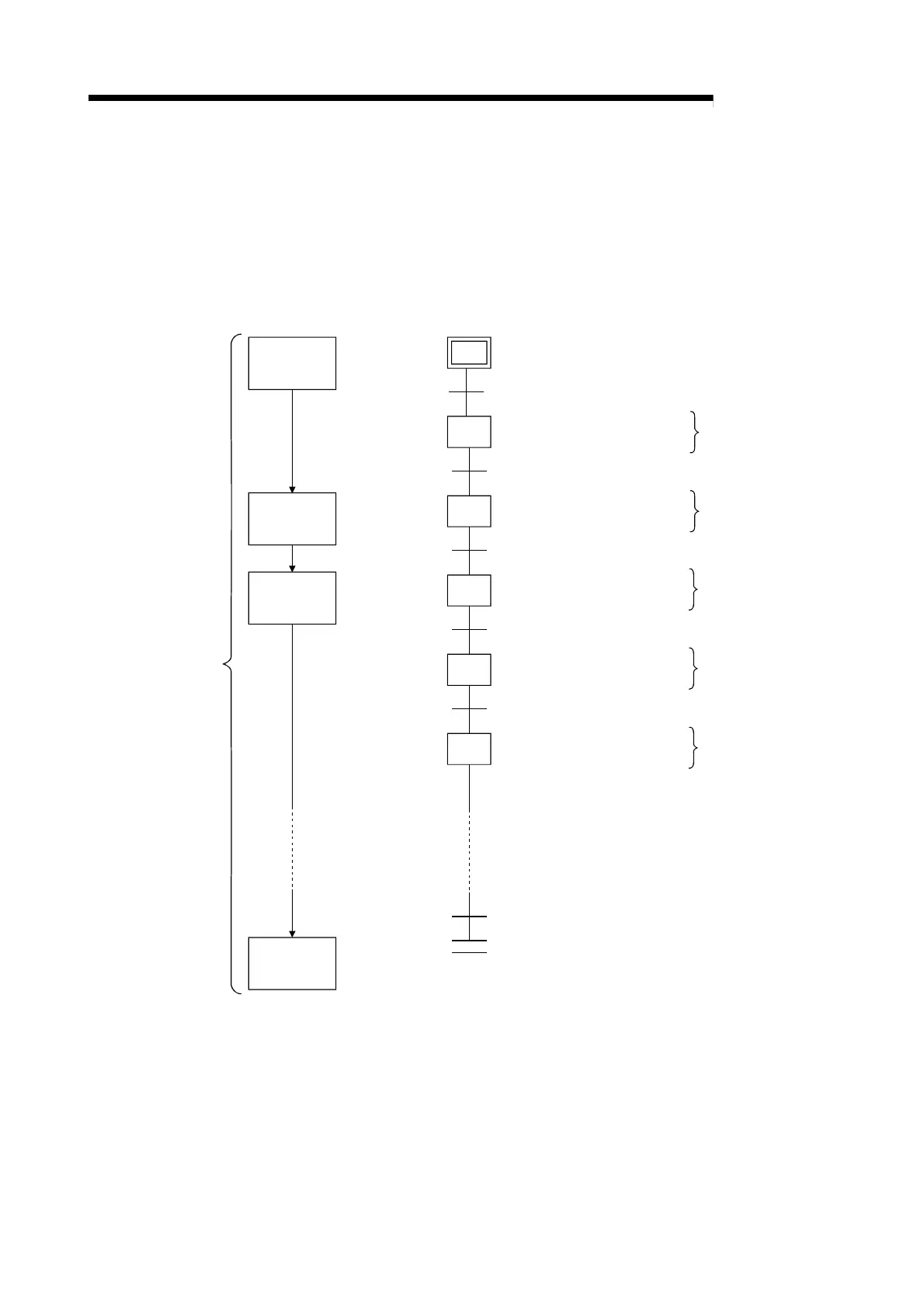
The SFC program consists of steps that represent units of operations in a series of machine
operations.
In each step, the actual detailed control is programmed by using a ladder circuit.
Grouping steps into one block in process units allows to create an SFC program that is capable of
tracking all the processes as well as structuring the operation flow in each process.
Workpiece
detection
Workpiece
loading
Drilling
operation
Machining
completed
Whole process
Workpiece unloaded confirmation
aX0 & aX1
oY20
aX2
oY21
aX3
oY22 ,PLS M0
pM0
rY23, oT0 K20
aX7
sY23
aX4
END step
Initial step
Transition
condition 0
step 1
Transition
condition 1
step 2
Transition
condition 2
step 3
Transition
condition 3
step 4
step 5
Transition
condition n
START switch, Workpiece detection
Conveyor START
Clamp confirmation
Pallet clamp
Drill rotation
Drill DOWN
Drill Down stop
Pallet detection
Drill DOWN endpoint
1 operation unit
1 operation unit
1 operation unit
1 operation unit
1 operation unit
[Process flow chart] [SFC diagram]
[Operation output/transition condition]
Transition
condition 4
The SFC program performs a sequence of operations, beginning from the “initial” step,
proceeding to each subsequent step as the transition conditions are satisfied, and ending at the
“END” step.
(1) When the SFC program is started, the “initial” step is executed first.
(2) Execution of the initial step continues until transition condition 0 is satisfied. When this
transition condition is satisfied, execution of the initial step is stopped, and processing
proceeds to the step which follows the initial step.
Processing of the SFC program continues from step to step in this manner until the END step has
been executed.

 Loading...


