3 - 7 3 - 7
3 SPECIFICATIONS
MELSEC-Q
3.2 Device List
3.2.1 Device list of Basic model QCPU
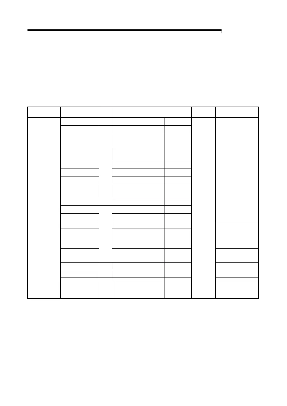
Table 3.3 indicates the devices that can be used for the transition conditions and operation
outputs of an SFC program.
Table 3.3 Device List
Classification Device Type Expression
User
Assignment
Remarks
Special relay Bit SM0 to SM1023 Decimal
Internal system
devices
Special register Word SD0 to SD1023 Decimal
Fixed
Input X0 to X07FF Hexadecimal
• Direct processing at
DX
Output Y0 to Y07FF Hexadecimal
• Direct processing at
DY
Internal relay M0 to M8191 Decimal
Latch relay L0 to L2047 Decimal
Annunciator F0 to F1023 Decimal
Edge triggered
relay
V0 to V1023 Decimal
Link relay
Bit
B0 to B07FF Hexadecimal
Data register D0 to D11135 Decimal
Link register
Word
W0 to W07FF Hexadecimal
Normal timer T0 to T511 Decimal
Retentive timer ST0 to ST511 Decimal
• Set retentive timers
(ST) in parameter.
• Contact and coil are
bit devices.
Counter
Bit/
word
C0 to C511 Decimal
• Contact and coil are
bit devices.
Special link relay Bit SB0 to SB03FF Hexadecimal
Special link register Word SW0 to SW03FF Hexadecimal
Internal user
devices
Step relay Bit
S0 to S127/1 block (total
of 2048 points for all
blocks)
Decimal
Variable
within a
total of 16k
words
• Exclusively for SFC
program

 Loading...


