18 | Patching Examples
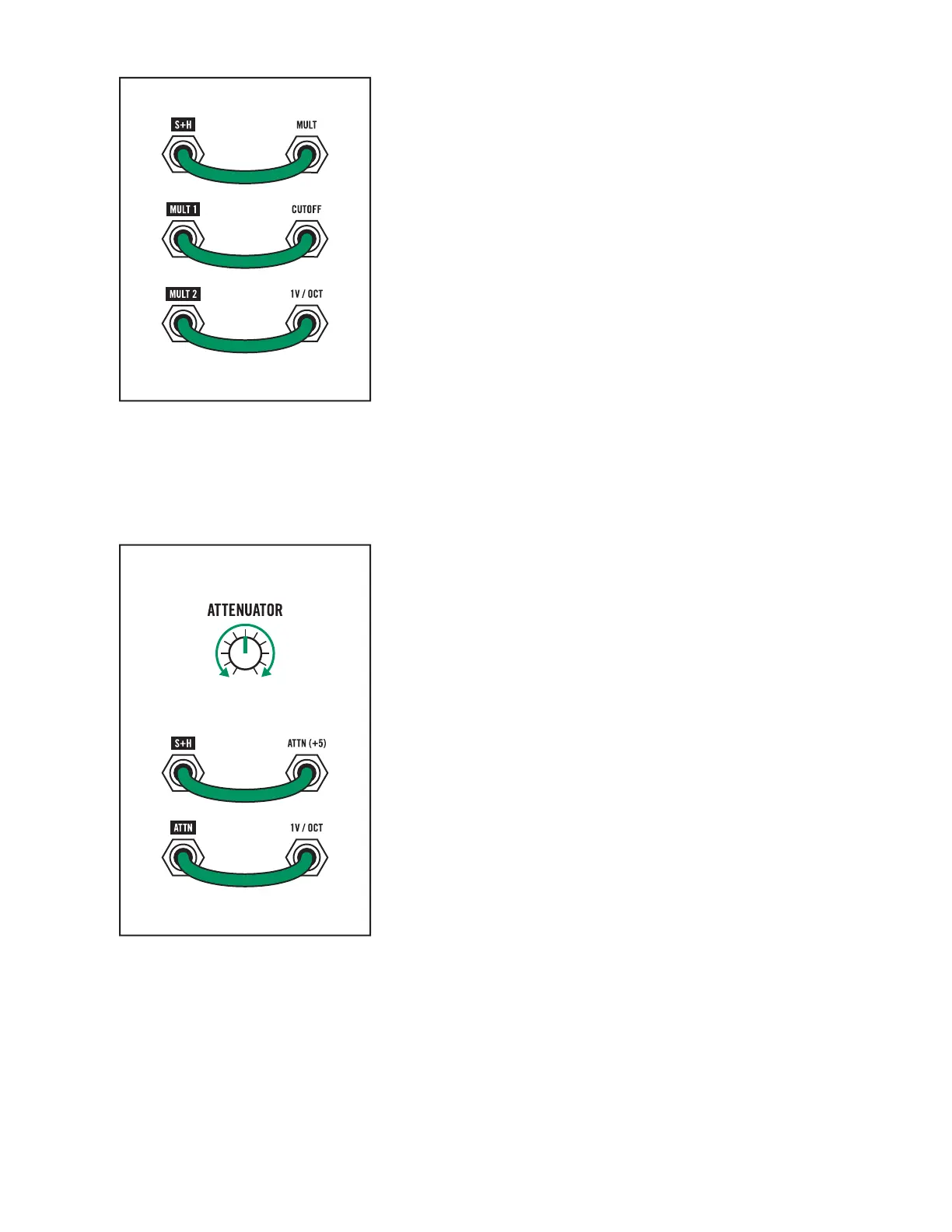
MULT
The MULT is a simple module that allows you to route one
signal to two dierent destinations. Continuing from the
SAMPLE + HOLD example above, you may want to route the
S+H eect to change the frequency of the VCO in addition
to the filter cuto. Patch the S+H output jack (R7; C2) to
the MULT input jack (R8; C1).
By patching the MULT 1 output jack (R8; C2) to the filter
CUTOFF input jack (R3; C2) we can replicate the example from
the previous section while having another copy of the Sample +
Hold signal available at the MULT 2 output jack (R8; C3).
Patch the MULT 2 output jack (R8; C3) to the 1V/OCT input jack
(R2; C1) to have the Sample + Hold change both the pitch and
filter cuto frequency at the same time.
ATTENUATOR
The ATTENUATOR is another simple module that allows you
to adjust the strength of any signal. Perhaps we want to use the
Sample + Hold to change the VCO frequency but would like a
less dramatic eect.
Patch the S+H output jack (R7; C2) to the ATTN (+5) input jack
(R6; C3) and patch the ATTN output (R7; C3) to the 1V/OCT
input jack (R2; C1).
With this configuration, you can use the ATTENUATOR knob
to scale the Sample + Hold eect on the VCO—from narrow,
subtle changes with the knob counter clockwise to wider
range changes as the knob is turned clockwise.

 Loading...