44 | Patchbay Module Functions
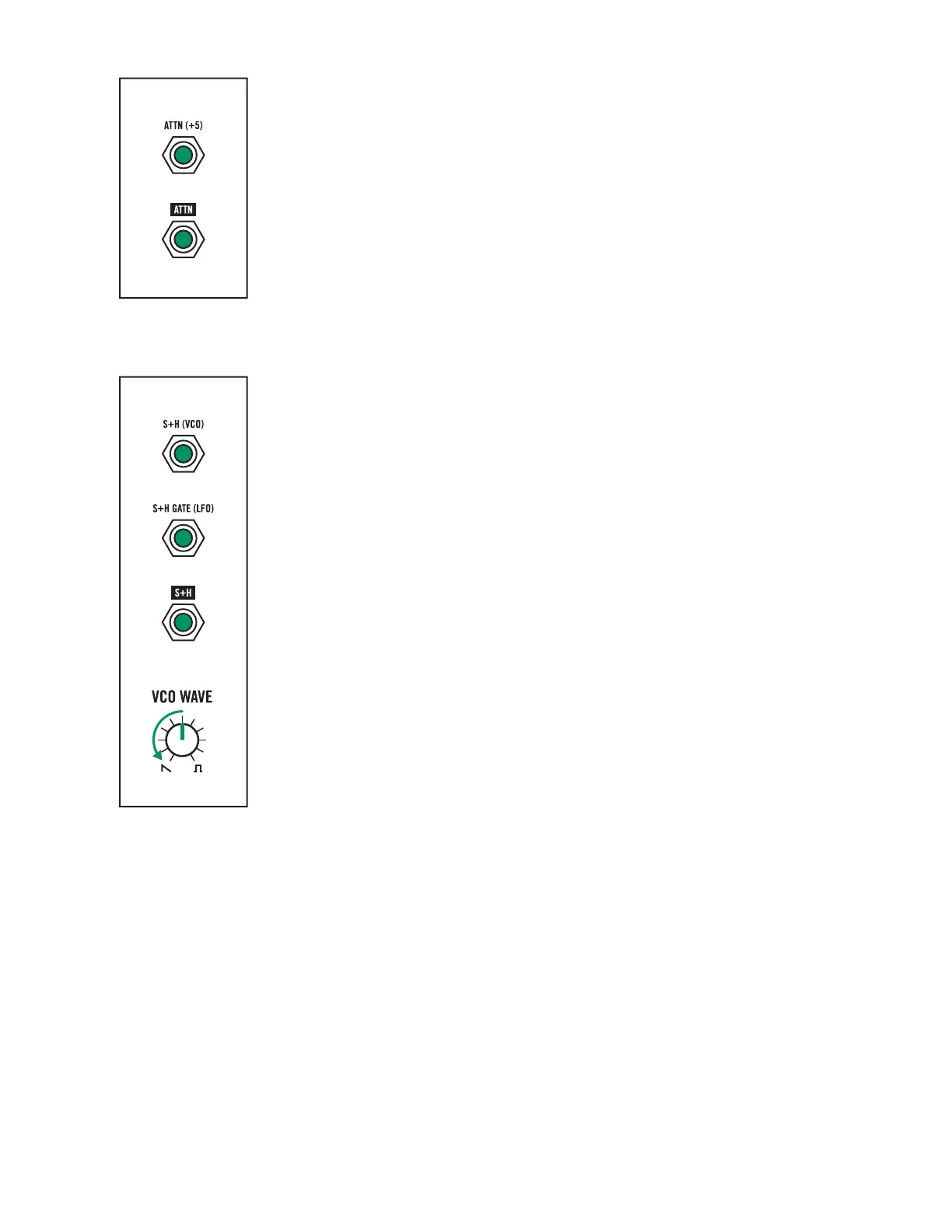
ATTENUATOR
The Attenuator can reduce the level of any signal connected to the ATTN (+5)
input jack (R6; C3). The attenuated signal is available at the ATTN output jack
(R7; C3).
NOTE: With nothing connected to the ATTN (+5) input jack, the ATTN output jack
can provide an available oset voltage from 0 Volts to +5 Volts, by adjusting the
ATTENUATOR knob.
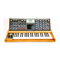
SAMPLE + HOLD
Sample + Hold is a specialized form of modulation that creates a series of
stepped voltages that can be applied to change the value of a specific parameter.
A Sample + Hold circuit has two inputs: a signal input—S+H (VCO) (R5; C2)—and
a gate input—S+H GATE (LFO) (R6; C2). When the gate input goes high, the
Sample + Hold circuit looks at the voltage at its signal input, grabs the precise
voltage value at that instant, and holds it. This held voltage is available at the S+H
output jack (R7; C2) until the next time the gate input goes high, whereupon a
new voltage value will be sampled from the signal input and held.
By default, Mavis uses the VCO as the sample source. When using the VCO as
the Sample + Hold source, keep in mind that the saw wave will provide a much
broader range of voltages to sample from than the square wave—as the saw
moves linearly between -5 Volts and +5 Volts, while the square jumps between
-5 and +5 Volts. Turning the VCO WAVE knob to saw will therefore have a much
more pronounced eect. An alternative source may be connected to the Sample
+ Hold signal input via the S+H (VCO) input jack (R5; C2).
The LFO is the default gate source connected to the Sample + Hold gate input.
It will sample a new voltage from the Sample + Hold signal source every time the
LFO goes high. An alternative source may be connected to the S+H GATE (LFO)
input jack (R6; C2).