28
WAVEFORM MODULATION
These modulation parameters affect the waveform of the Oscillators. Both knobs are applying LFO 3 to
the Oscillator wave shape.
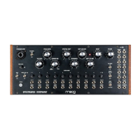
WAVE ANGLE / LFO 3 AMT (0 to 10)
Turning this knob determines the amount of LFO 3 that is applied as a
modulation source to the Oscillators’ Wave Angle parameter. The higher
the value of this knob, the deeper the effect.
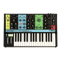
PULSE WIDTH / LFO 3 AMT
(0 to 10)
Turning this knob determines the amount of LFO 3 that is applied as a
modulation source to the Oscillators’ Pulse Width parameter. The higher
the value of this knob, the deeper the effect.
FM (FREQUENCY MODULATION)
Frequency Modulation (FM) allows the output of one oscillator to modulate the frequency of another
oscillator. Applying FM can produce complex sounds and introduce interesting harmonics. Moog One
uses linear FM.
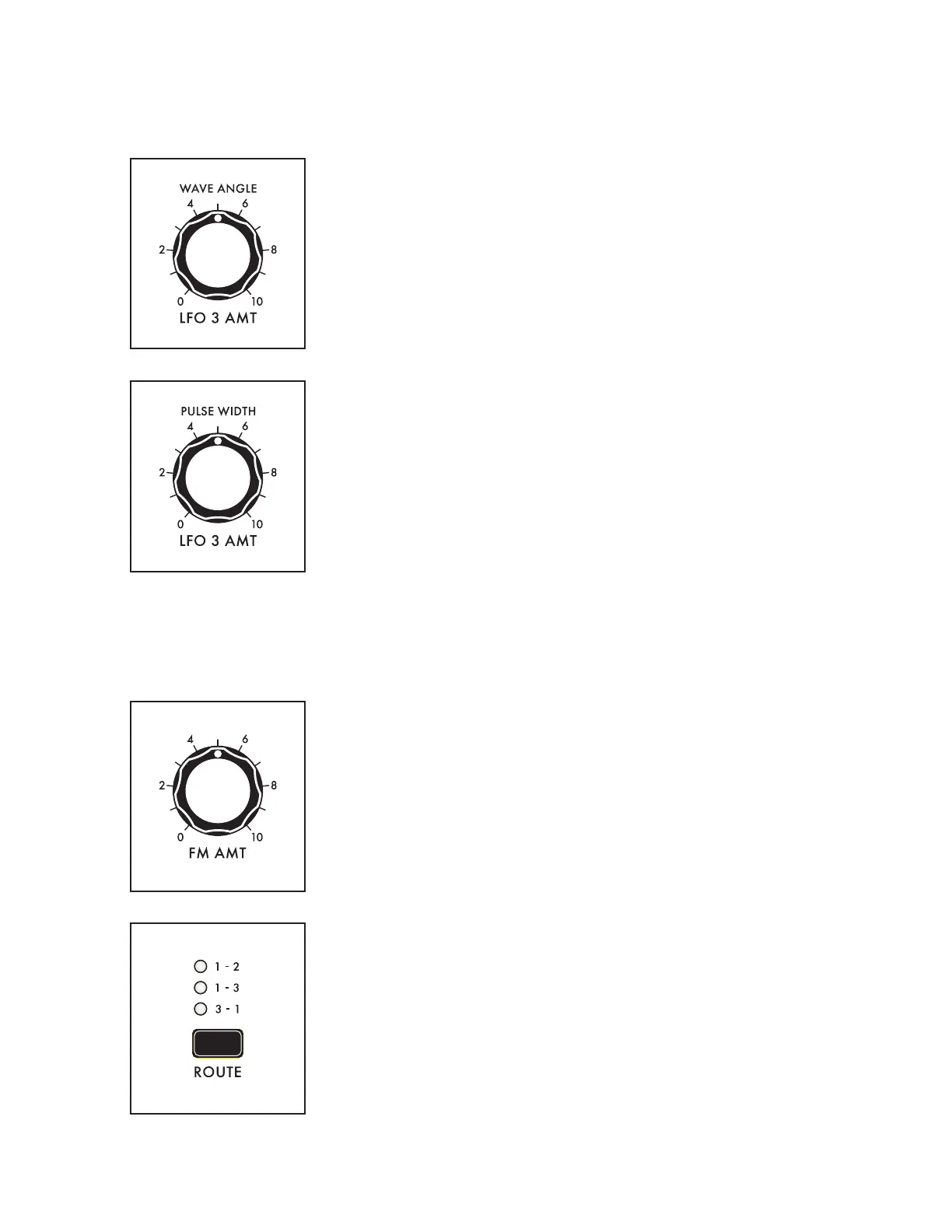
FM AMT (0 to 10)
Turning this knob determines the amount of Frequency Modulation that
is applied from one Oscillator to another. The higher the value of this
knob, the deeper the effect.
ROUTE (1 – 2, 1 – 3, 3 – 1)
This button selects the Oscillators and routing scheme for the FM effect.
When making a selection, the corresponding LED will light.
1 – 2
The output of Oscillator 1 is modulating the frequency of Oscillator 2.
1 – 3
The output of Oscillator 1 is modulating the frequency of Oscillator 3.
3 – 1
The output of Oscillator 3 is modulating the frequency of Oscillator 1.

 Loading...