31
MIXER
The Moog One Mixer module provides six input channels and two output busses. The rst ve inputs – OSC
1, OSC 2, OSC 3, RING MOD, and NOISE – have dedicated hardware Mixer controls on the Front Panel.
NOTE: Pressing the Mixer MORE button provides access to the sixth channel – the External Audio Input.
One of the Mixer output busses feeds into the State Variable Filter (SVF), the other into the Moog Ladder
Filter. Each input can be bussed to either Filter – or both – using the SVF and LADDER buss buttons.
Each Mixer Channel features a volume knob. Rotate the knob to the right to raise the level, rotate the knob
to the left to lower the level. At the lowest setting (farthest to the left), no signal is entering the mixer.
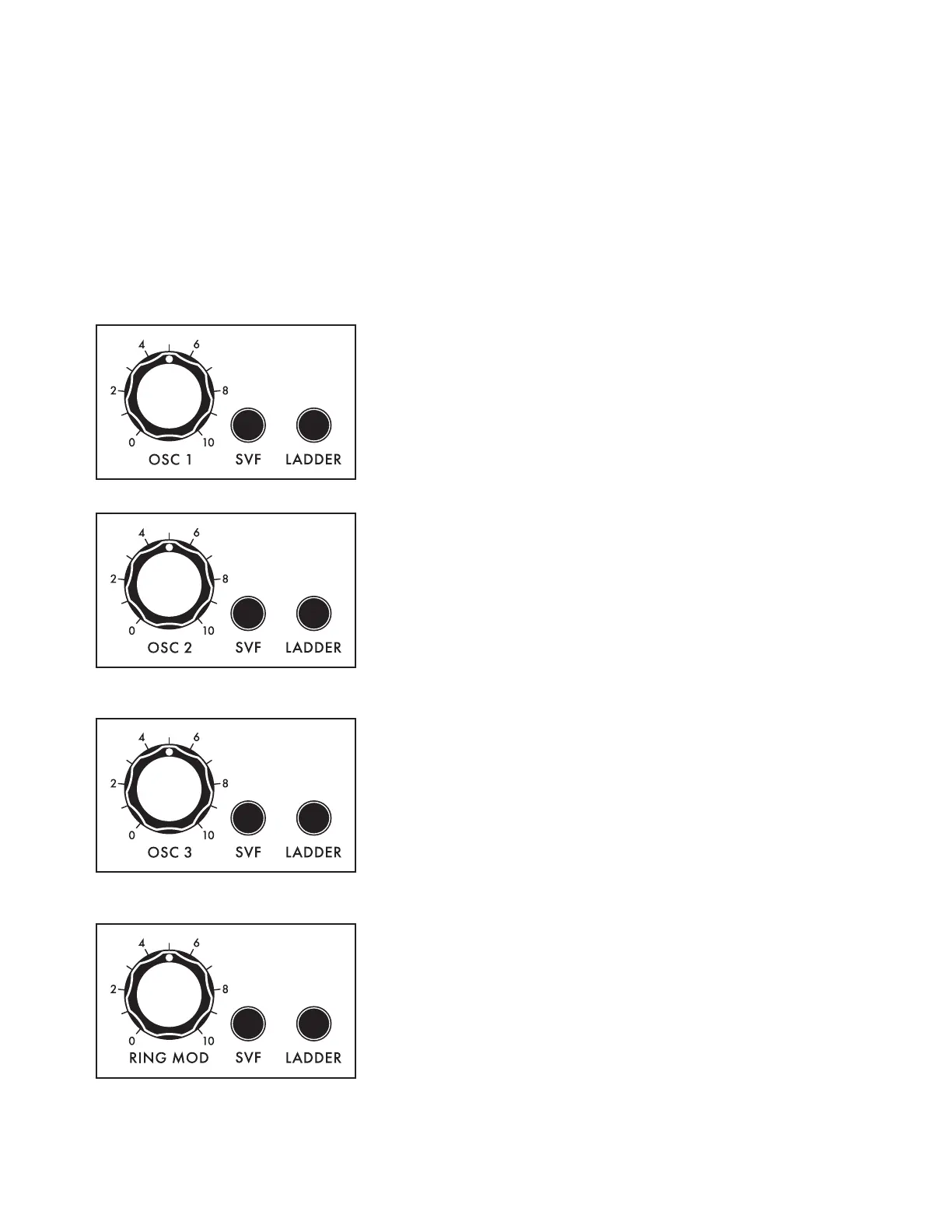
OSC 1
Use the OSC 1 knob to set the level of the Oscillator 1
signal as it enters the Mixer. Press the associated SVF and
LADDER buttons to specify which FILTE R(s) Oscillator 1 is
being routed to. When an SVF and/or LADDER button is lit,
it is On, and that lter path is enabled.
OSC 2
Use the OSC 2 knob to set the level of the Oscillator 2
signal as it enters the Mixer. Press the associated SVF and
LADDER buttons to specify which FILTE R(s) Oscillator 2
is being routed to. When the button is lit, it is On, and that
lter path is enabled.
OSC 3
Use the OSC 3 knob to set the level of the Oscillator 3
signal as it enters the Mixer. Press the associated SVF and
LADDER buttons to specify which FILTE R(s) Oscillator 3 is
being routed to. When each button is lit, it is On, and that
lter path is enabled.
RING MOD
Use the RING MOD knob to set the level of the Ring
Modulator signal as it enters the Mixer. Press the associated
SVF and LADDER buttons to specify which FILTER(s) the
Ring Modulator is being routed to. When each button is lit,
it is On, and that lter path is enabled.

 Loading...