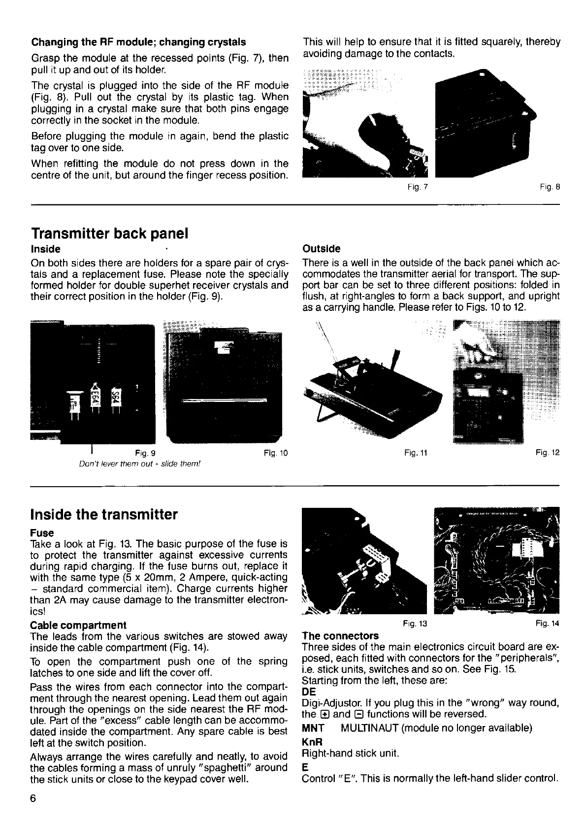
Changing the
RF module;
changing crystals
Grasp the
module
at
the recessed
points (Fig.
7), then
oull
it
uo and
out of its holder.
The crystal is
plugged
into the side of the
RF module
(Fig.
8). Pull out the crystal by its
plastic
tag.
When
plugging
in a crystal make sure that both
pins
engage
correctly
in
the socket
in
the
module.
Before
plugging
the module in
again,
bend the
plastic
tag over to one side.
When
relitting the module
do
not
press
down
in the
centre
of the
unit,
but
around
the finger recess
position.
This will help to ensure that
it is fitted
squarely,
thereby
avoiding damage to the contacts.
Ftg.7
Transmitter back
panel
lnside
On
both sides there are holders for a spare
pair
of crys-
tals
and
a replacement fuse. Please note the specially
formed
holder for
double superhet
receiver
crystals
and
their correct
position
in
the
holder
(Fig.
9).
Don't lever them out
-
slide them!
Outside
There is a well in the outside of the back
panel
which ac-
commodates
the transmitter aerial Ior transport. The sup-
port
bar can be set
to three ditferent
positions:
folded in
flush, at right-angles to
form
a back support, and upright
as a carrying
handle. Please refer to
Figs. 10
to
12.
\
Fig. 11
Fil.12
lnside the
transmitter
Fuse
Take a
look
at
Fig. 13. The basic
purpose
of
the fuse is
to
protect
the
transmitter against excessive currents
during
rapid charging.
lf the fuse burns out, replace
it
with the same
type
(5
x 21mm,2 Ampere,
quick-actjng
-
standard
commercial item). Charge currents
higher
than
2A may cause damage
to the transmitter electron-
ics!
Cable compartment
The leads from
the various switches are stowed away
inside
the
cable
compartment
(Fig.
14).
To open the compartment
push
one of the spring
latches to one side
and lift the cover off.
Pass the
wires from each connector
into the comparl
ment through the
nearest opening. Lead them out again
through
the openings on the side
nearest the RF
mod-
ule.
Part of the
"excess"
cable length can be accommo-
dated
inside the compartment.
Any spare cable
is best
left at the switch
position.
Always arrange
the wires carefully and
neatly, to
avoid
the cables
forming a mass of unruly
"spaghetti"
around
the stick units
or close to
the keypad cover well.
6
Fig. 13 Fig.
14
The connectors
Three
sides
of the main electronics circuit
board
are
ex-
posed,
each fitted
with
connectors
for the
"peripherals",
i.e.
stick units,
switches and so on. See
Fig. 15.
Starting
from the
lefl,
these are:
DE
Digi-Adjustor. lf
you plug
this
in
the
"wrong"
way round,
the
El
and
E
f
unctions
will be reversed.
MNT MULTINAUT
(module
no longer available)
KnR
Right-hand stick unit.
E
Control
"E".
This is normally
the left-hand slider control.
Fig.
14
 Loading...