The
final
job
is to apply the self-adhesive
stickers in the
deoressions
next to the switches.
Remove
each
sticker
in turn, using a
pair
of tweezers or
fine-nosed
pliers,
place
it in the depression
in the switch
panel,
and
press
it
down
firmly
(Fig.
54).
lf we have not
provided
a sticker
printed
with
your particular
application, use the all-yel-
low stickers and
wnte
the
inscription with a felttip
pen.
Fig.54
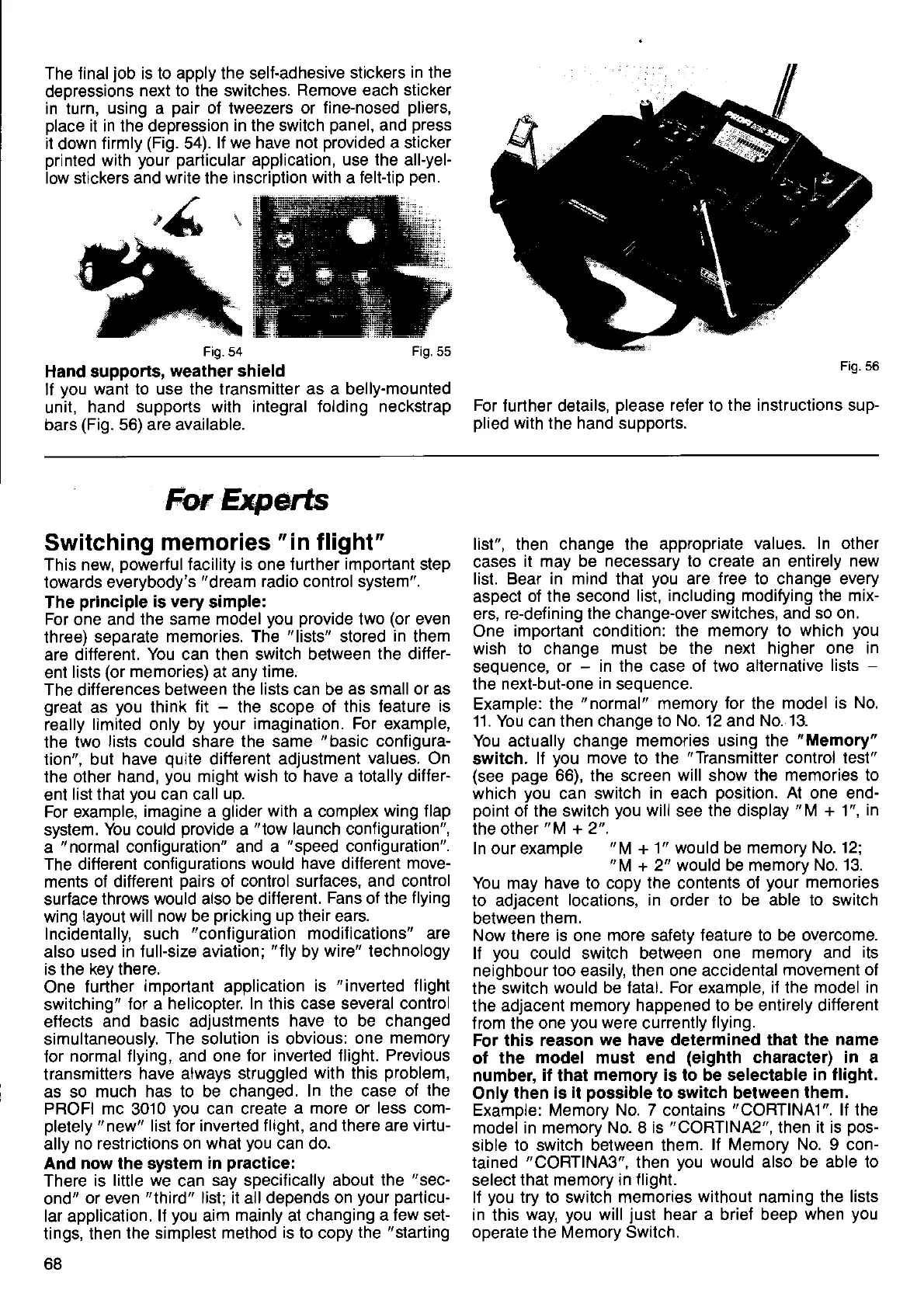
Hand supports,
weather shield
lf
you
want to use the transmitter as a belly-mounted
unit,
hand supports
with integral folding neckstrap
bars
(Fig.
56) are
available.
Fig.56
For further details,
please
refer to the instructions sup-
plied
with the hand supports.
Frg.55
fur
$rperts
Switching
memories
"in
flight"
This new,
powerful
facility is one turther important step
towards everybody's
"dream
radio control system".
The
principle
is very simple:
For one and
the same model
you
provide
two
(or
even
three)
separate
memories. The
"lists"
stored
in
them
are different.
You can then switch between
the differ-
ent
lists
(or
memories)
at
any time.
The
differences
between the
lists
can be
as small or as
great
as
you
think
fit
-
the scope
of this teature is
really
limited only by
your
imagination. For example,
the two
lists could share the same
"basic
configura-
tion", but
have
qurte
diflerent adjustment
values. On
the other
hand,
you
might wish to have a totally differ-
ent
list that
you
can call up.
For example,
imagine a
glider
with
a complex
wing f lap
system.
You could
provide
a
"tow
launch configuration",
a
"normal
configuration" and
a
"speed
configuration".
The different configurations
would have different
move-
ments
of different
pairs
of
control
surtaces, and control
surface
throws
would
also be
difterent. Fans of the
flying
wing
layout will now be
pricking
up their ears.
Incidentally, such
"configuration
modifications" are
also used
in full-size aviation;
"f
ly
by
wire" technology
is the
key
there.
One
further
important application is
"inverted
flight
switching"
for a
helicopter. In this case several control
eflects
and basic adjustments
have to be changed
simultaneously.
The
solution
is obvious: one
memory
for
normal flying, and one
for inverted tlight.
Previous
transmitters
have
always
struggled
with
this
problem,
as so
much has to be changed.
In the case of
the
PROFI
mc 3010
you
can create
a more or less com-
pletely
"new"
list tor inverted
flight, and there are
virtu-
ally
no restrictions on
what
you
can
do.
And now the system
in
practice:
There is
little we
can
say specifically about
the
"sec-
ond"
or even
"third"
list; it all depends on
your particu-
lar application.
lf
you
aim
mainly
at changing
a few set-
tings, then
the
simplest
method
is
to copy
the
"starting
68
list", then change the appropriate
values. In other
cases
it may be necessary to create an
entirely new
list. Bear in mind that
you
are
free
to change
every
aspect
of the second list,
including modifying the mix-
ers,
re-defining the change-over switches, and so
on.
One
important
condition:
the memory to
which
you
wish to change
must
be
the next higher one in
seouence.
or
-
in the case o1 two alternative
lists
-
the next-but-one
in
seouence.
Example:
the
"normal"
memory
for
the
model is No.
11. You
can
then change to No. 12 and
No. 13.
You actually change
memories using the
"Memory"
switch.
lf
you
move
to
the
"Transmitter
control test"
(see
page
66), the screen
will
show
the memories to
which
you
can switch
in each
position.
At
one end-
point
of the switch
you
will
see
the display
"M
+ 1",
in
the other
"M
+ 2".
In our example
"M
+ 1" would be memory
No. 12;
You may have to copy
the
contents
of
your
memories
to adjacent
locations, in order to be able to switch
between
them.
Now there
is
one
more
safety
feature to be overcome.
lf
you
could switch between
one memory and
its
neighbour too easily, then one accidental
movemenl of
the switch
would be fatal. For examole,
if
the
model in
the adjacent
memory happened to be entirely different
from the one
you
were
currently
flying.
For this reason
we have
determined
that the name
of
the model must end
(eighth
character) in a
number,
il
that
memory is to be selectable
in flight.
Only
then is
it
possible
to
switch
between them.
Example: Memory
No. 7
contains
"CORT|NA1".
lf the
model in memory
No.8 is
"CORT|NA2",
then it is
pos-
sible
to switch between them.
lf Memory No.9 con-
tained
"CORTINA3",
then
you
would also be able to
select
that memory in
flight.
lf
you
try to switch memories
without naming the lists
in this
way,
you
will
just
hear a brief beep
when
you
operate the Memory Switch.
 Loading...