F
Control
"F".
This
is normally the
right-hand slider control.
T
Keypad.
Can be
plugged
in either
way round.
G
Control
"G".
Normally this
is
a switched
channel.
Plug it
in the opposile
way round and
the direction of
operation
ol the switched
channel
is reversed.
H, l
Controls
cial
purposes.
Not used
in the standard
version.
KnL
Left-hand
stick unit.
51 to
55
Inputs for the change-over/coupling
switches
51 to 55.
More
on this on
page
12.
US
Teacher/Pupil
switch.
lf
you
install a switch
for
Teacher/Pupil
operation
(the
buddy box system),
it must
be
plugged
in here.
M
Memory switch.
lf a switch
is installed
for
this
purpose,
it must
be
plugged
in here. Plug it
in
the
"wrong"
way
round and
the selected
memories are interchanged.
Note:
When connecting auxiliary
controls and
switches
please
refer to the explanation
of the
"TEST
Controls"
menu on
page
66.
Activating
the stick
ratchet
As supplied, both
vertical axes
of the dual-axis
stick
units
are self-neutralising.
Most modellers
will want to
remove the self-neutralising
action
trom one
stick
(the
"throttle"
stick), and activate
the ratchet
instead.
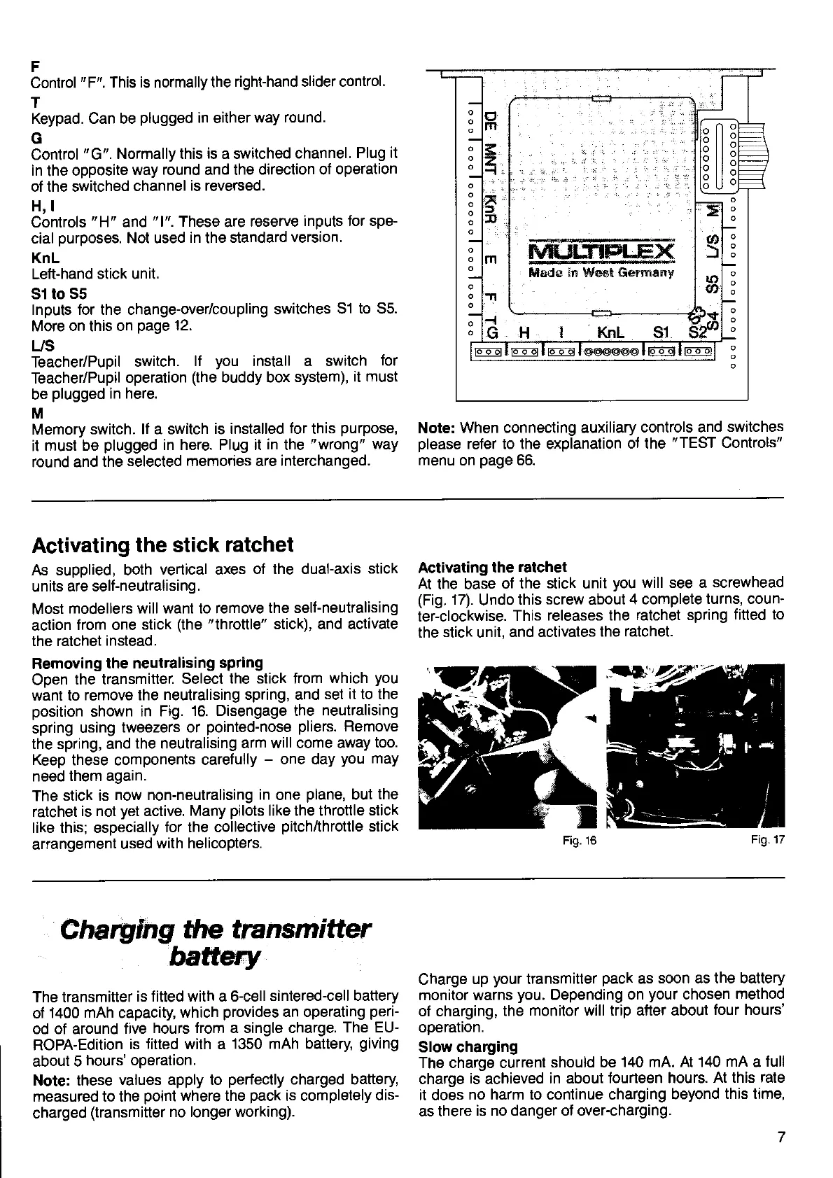
Removing
the
neutralising spring
Open
the transmitter.
Select
the stick from
which
you
want to
remove the
neutralising spring, and set
it to the
position
shown
in
Fig. 16. Disengage the
neutralising
spring
using
tweezers or
pointed-nose
pliers.
Remove
the spring, and
the neutralising
arm will come
away too.
Keep these
components carefully
-
one day
you
may
need
them again.
The stick
is
now non-neutralising
in one
plane,
but
the
ratchet
is not
yet
active.
Many
pilots
like the throttle
stick
like this; especially
for the collective
pitch/throttle
stick
arrangement
used
with helicopters.
Activating
the
ratchet
At the base
of the stick unit
you
will see
a screwhead
(Fig.
17).
Undo
this screw about
4 complete
turns, coun'
ter-clockwise.
This
releases the
ratchet spring
fitted to
the stick unit,
and activates
the ratchet.
Fig. 16
Fig.17
Charylng
the transm
itter
batt*y
The transmitter
is fitted with a 6-cell sintered-cell
battery
of
1400 mAh capacity,
which
provides
an operating
perF
od of around
five
hours trom a single charge.
The EU-
ROPA-Edition
is {itted with a
1350 mAh battery
giving
about
5
hours' operation.
Note: these
values apply to
perfectly
charged
battery,
measured to lhe
point
where
the
pack
is completely
dis-
charged
(transmiüer no longer working).
Charge
up
your
transmitter
pack
as soon
as the battery
monitor warns
you.
Depending on
your
chosen
method
of charging,
the monitor
will trip after about
tour hours'
operalron.
Slow
charging
The charge current
should be
140 mA. At
140 mA
a
full
charge
is achieved in about
fourteen hours.
At this rate
it does
no harm to continue charging
beyond
this time,
as there
is no danger ol over-charging.
 Loading...