In this Section
you
will
get
to know the
mixers which the
transmitter has to otfer.
Before
you
dive in here,
please
make sure that
you
are
familiar with the simpler setting-up tasks, such
as
assigning
transmitter controls and servos, adjusting
servo travel and direction and so on.
Practise these
oro-
cedures several
times until
you
teel at home with them.
In our examples we will
restrict
ourselves to
fixed-wing
model aircratt:
helicopters
are covered
in a separate
Section
(page
53).
Nevertheless, all the basic informa-
tion
we
provide
here applies
in full measure
to the spe-
cialised
helicooter mixers.
The
mixers
provided
by the PROFI mc 3010 are oper-
ated
in
a
rather
different
way from normal. We think that
this new type of
"operating
philosophy"
is much sim-
oler than
the
conventional
method.
For
this
reason we will first discuss our
new method
of
considering
mixers. You will see that the concept
fits in
elegantly
with
the simple and
logical overall concept of
the transmitter,
with which
you
are by now familiar.
After
this
we
describe
the characteristics of the
"pre-de-
fined mixers"
(explanation
later); the description
is
briel,
since eveMhing always works
in
the same
way.
Now, modellers
are by
nature inventive souls, and the
probability
is high that
somebody
will find he needs a
mixing function which our
programmer,
in
spite of
his
vast experience,
has not thought of beforehand. For this
reason there are the
"
User-detined
mixers"
("
USR-
MlX") which
you
can
"define"
yourself.
This
gives you
the
chance
lo overcome the most exotic
Droblems.
These
user-defined
mixers are discussed in the Jinal
Section.
What
is
"mixing"?
Let's imagine a simple case:
Your model is fitted with camber-changing
flaps or land-
ing flaps. They are
lowered for
the
landing approach,
and thereby
increase the lift coefficient of the wing.
However, one result of this is usually an alteration
in the
pitch
trim of the
model
-
it
becomes
nose-heavy or tail-
heavy.
The
pilot
then has to apply
"up/'
or
"down"
in
order to
keeo the model on an even keel.
This manual
form of
"pitch
trim compensation" can be
automated by
passing
a
proportion
of the
"flap
signal"
to the elevator. Of
course, this
has
to be
in the
correct
direction, and
ot a suitable
magnitude. You don't need
to
worry that this
part
of
the flap signal
"goes
missing";
the electronics
are designed
in
such a
way
that
the full
signal
reaches the flaps, even
when
part
of it is
"bled
off" to
the elevator.
The net result is that the elevator servo
receives
part
ot
the
"flap"
signal
in
addition
to its main
"elevator"
signal.
Fig.29
Now we will
refine the
arrangement
(and
complicate
it).
Your model
is
capable
of tlying smaller-diameter
loops if
the wing
flaps deflect down slightly
when
you
apply
up-
elevator. Once
again the
pilot
could do
it, but we will
remove that task
from him and automate the
process
by
teeding a
proportion
of the elevator signal
to the flap
servo.
The
net result is that the tlap servo
receives
part
of
the
"elevator"
signal in addition to
its main
"flap"
signal.
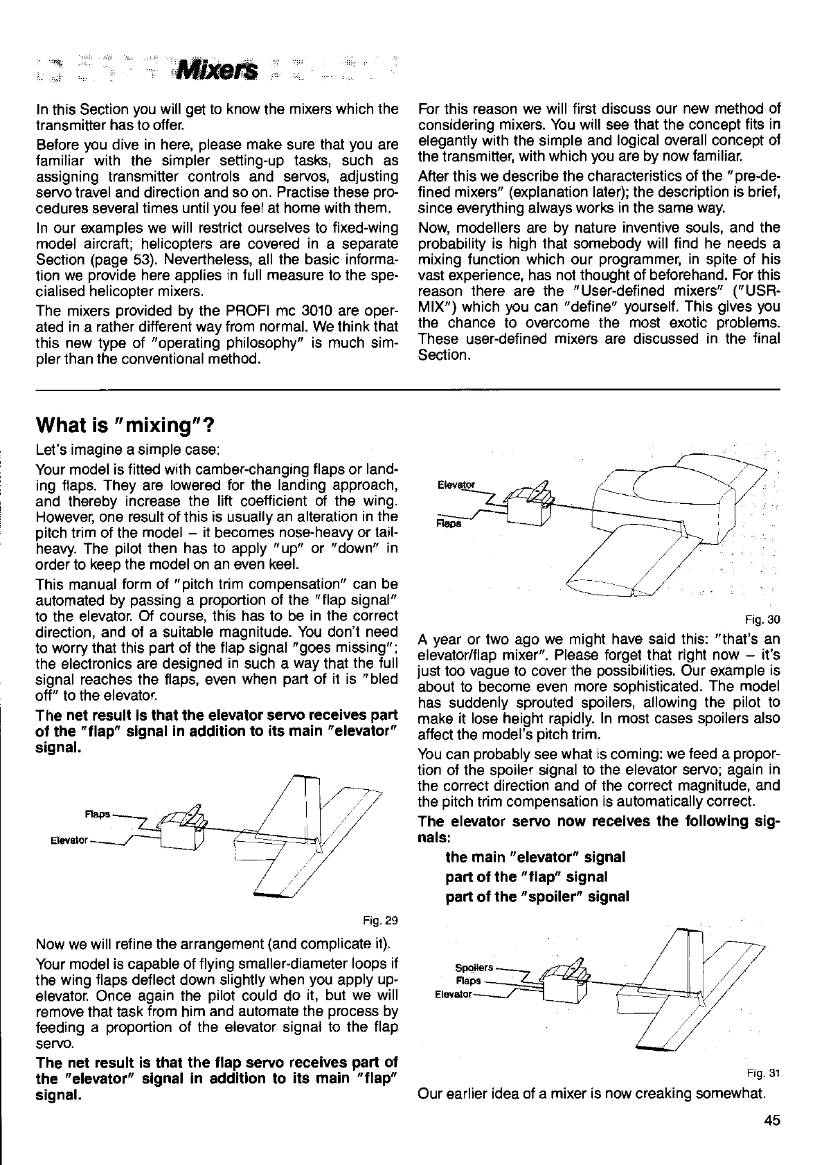
Fig.30
A
year
or two ago
we might have said this:
"that's
an
elevator/flap
mixer". Please
lorget
that
right now
-
it's
just
too vague to cover lhe
possibilities.
Our example
is
about to become even
more soohisticated.
The model
has suddenly sprouted spoilers,
allowing the
pilot
to
make
it lose height rapidly. In most cases spoilers also
affect the
model's
pitch
trim.
You can
probably
see
what is
coming:
we feed a
propor-
tion oJ the spoiler
signal to the elevator servo; again
in
the
correct
direction and of the correct
magnitude, and
the
pitch
trim compensation
is automatically correct.
The elevator servo
now receives the
following
sig-
nals:
the main
"elevator"
signal
part
ot the
"tlap"
signal
part
of
the
"spoiler"
signal
Fig.
Our earlier
idea of a mixer is now creaking somewhat.
45
 Loading...