EasyManua.ls Logo

Navico BR24 User Manual

Navico BR24
34 pages
To Next Page IconTo Next Page
To Previous Page IconTo Previous Page
Page #10 background imageLoading...
Page #10 background image
Radar system overview
The Navico Broadband radar is a state of the art navigation aid. It provides outstanding radar
performance without the limitations of conventional pulse radars such as: dangerous high power
microwaves, standby warm up time, 30 m blind spot (mainbang), high power consumption and
large open arrays - which is what would be required to obtain the same image quality at shorter
ranges.
The Navico Broadband radar has an effective range from 200 ft to 24 nm and has an operating
power consumption of 17 W and stand-by power consumption of 1.6 W.
The system consists of: radar scanner, an interface box and an interconnection cable. The
scanner is housed in a dome of similar size to most 2 kW radars on the market.
The interface box is used to connect displays, power and heading information. There are two
models: RI10 and RI11. Depending on the display system used, the main difference is that -
one has a SimNet (Simrad NMEA 2000) connector for heading input (RI10). The other interface
box (RI11) has a connector to interface to RS422 displays and NMEA 0183 heading sensors.
Both interface boxes have a Network connector to interface to Ethernet displays.
Lowrance HDS units sold in the USA do not require an interface box and the scanner connects
directly to the display or Ethernet switch
Brand Model Radar interface
box used
Data connection
protocol
Chart overlay MARPA
Lowrance HDS USA N/A Ethernet Yes* No
Lowrance HDS R.O.W RI11 Ethernet Yes* No
Simrad GB40 RI10 Ethernet Yes* Yes**
Northstar 8000i RI11 Ethernet Yes* Yes**
Northstar 8000i + N2k RI10 Ethernet Yes* Yes**
Northstar M series RI11 RS422 Yes* No
Simrad NX40/45 RI11 RS422 Yes* No
*For best chart overlay performance use a heading sensor. Course over ground can be used but
only when moving
** For MARPA it is essential to use a heading sensor with an output speed of 10 Hz. Heading
sensor needs to be a rate gyro stabilized compass or better.
8 | Introduction to the Navico Broadband radar system
Question and Answer IconNeed help?

Do you have a question about the Navico BR24 and is the answer not in the manual?

Navico BR24 Specifications

General IconGeneral
BrandNavico
ModelBR24
CategoryMarine Radar
LanguageEnglish

Summary

Preface

Industry Canada

Outlines conditions for device operation as per Industry Canada regulations.

FCC Statement

Details FCC compliance, limits, and user guidance for radio frequency emissions.

CE Compliance

Radar Transmit Emissions

Disclaimer

Warranty

Feedback from you

Introduction to the Navico Broadband radar system

Welcome

Congratulates the user and highlights the key features of the new radar system.

Install the radar

Choose the scanner location

Guides the user on selecting an optimal position for the radar scanner on the vessel.

Mounting the scanner

Provides step-by-step instructions for securely attaching the radar scanner unit using mounting hardware.

Mounting the radar interface box

Explains how to install the radar interface box in a suitable, dry location away from elements.

Wiring the radar system

Connect interconnection cable to the scanner

Details connecting the scanner interconnection cable to the radar scanner unit using a 14-pin connector.

Connect the interconnection cable to radar interface box

Guides the process of connecting the scanner cable to the radar interface box, ensuring proper sealing.

Connect the Broadband radar to your display

Illustrates various connection methods for Lowrance HDS displays and other Navico systems.

NX40, NX45 SimNet Heading

Details wiring for SimNet heading sensor connection with NX40/45 displays.

M84, M121 NMEA 0183 Heading

Explains NMEA 0183 heading sensor connection for M84/M121 displays.

GB40 SimNet Heading

Describes SimNet heading connection for the GB40 NavComputer.

8000i NMEA 0183 Heading

Details NMEA 0183 heading sensor connection for 8000i systems.

8000i SimNet / NMEA2000 Heading

Explains SimNet/NMEA2000 heading sensor connection for 8000i systems.

Connect power

Provides instructions for connecting the power supply to the radar system, covering both interface box and direct connections.

Configure displays to use radar

Lowrance HDS radar setup

Guides the setup and configuration of the radar on Lowrance HDS displays, including antenna height and bearing.

Simrad GB40 / Northstar 8000i radar setup

Details radar setup and bearing alignment for Simrad GB40 and Northstar 8000i displays.

Simrad NX40/45 or Northstar M84/M121 radar setup

Outlines the radar setup and zero bearing adjustment for NX40/45 and M84/M121 displays.

Drawings

Scanner dimensions

Provides detailed physical dimensions and mounting hole locations for the radar scanner unit.

Radar interface box

Shows the physical dimensions and connection layout of the radar interface box.

Maintenance

BR24 BroadBand radar scanner specifications

Navico Broadband radar part numbers

RF exposure compliance certificate

Description of Test Article

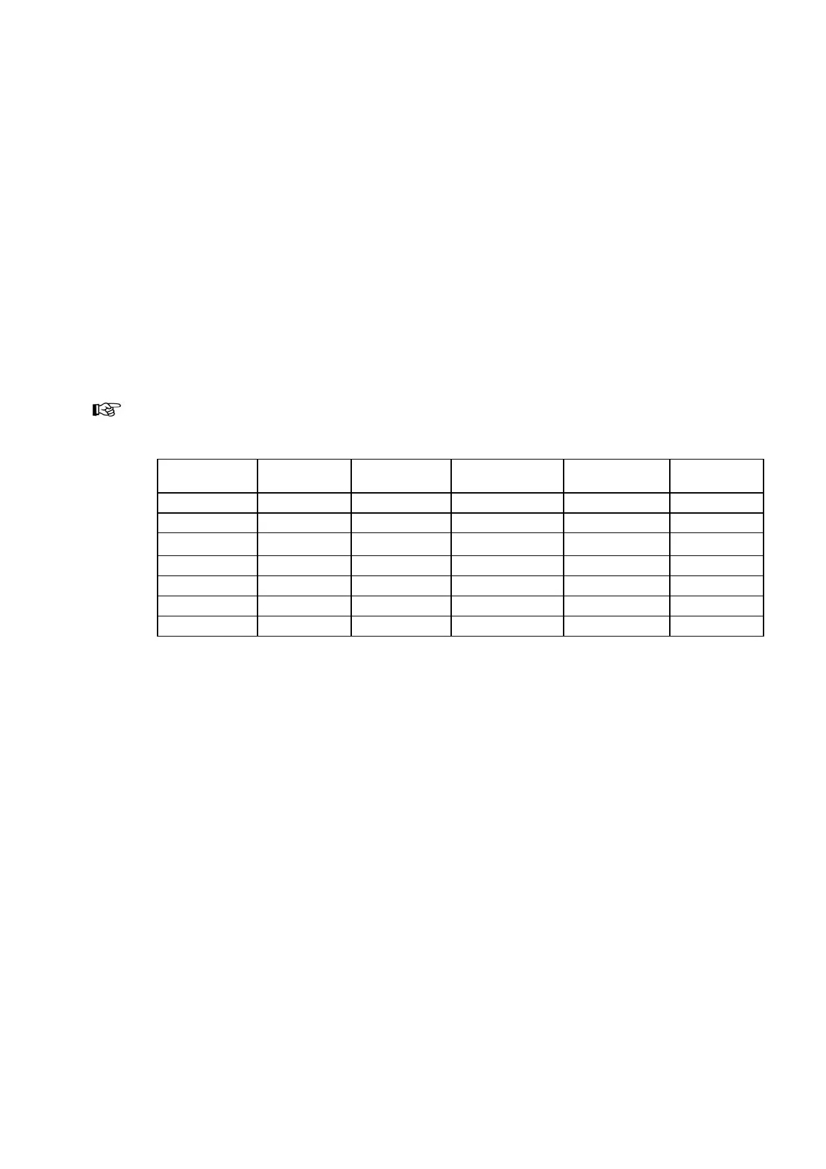
Details the test article's description, model number, operating frequencies, and power output for compliance testing.

Related product manuals