7-20
2.8 DDC circuit description
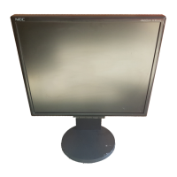
2.8.1 Analog circuit
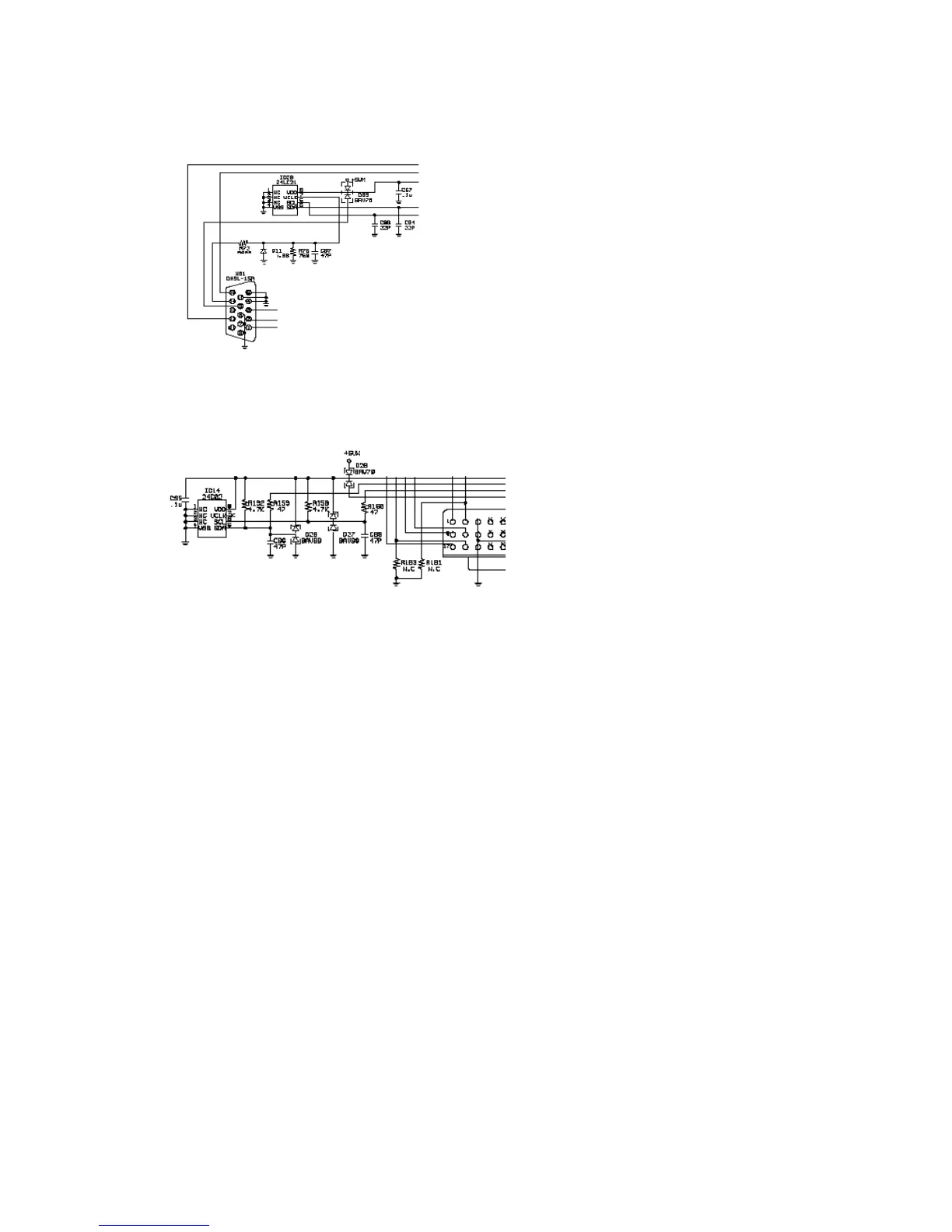
2.8.2 Digital circuit
2.8.3 General description
The EEPROM for DDC are two pieces (IC26, IC14) in analog and digital. The EDID of both IC are same data.
IC26 has DDC1 mode and DDC2B mode, but this circuit supported only DDC2B mode. IC14 only has
DDC2B.
The DDC2B communication uses the same line as Input 2 port. This mode activate at factory adjustment.
Therefore it is set into inactive in shipment. The DDC2B communication is processed in SUB-CPU.
Both Input port operates similar on DDC2B communication. Then following explanation is for D-SUB circuit.
When the power supply of the set is turned OFF, the VDD of IC26 is applied to Pin 9 of W01 and power is
through the D09. When the power supply of the set is turned ON, VDD is applied to IC22 through D09. Same
principle of IC14.
 Loading...