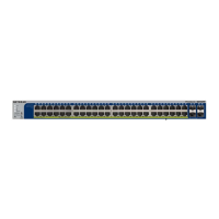
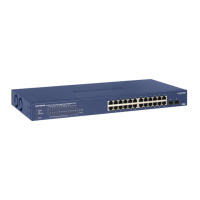
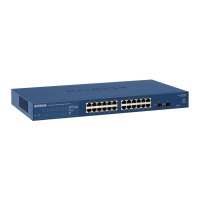
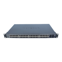
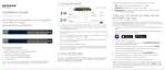
LEDs
This section describes the LEDs on the front panel of the switch.
Table 2. Front panel LEDs
DescriptionLED
Solid green.The switch is powered on.
Solid yellow.The switch is starting.
Off. Power is not supplied to the switch.
Power LED
Solid yellow.The internal fan failed.
Off.The internal fan is operating normally.
Fan LED
Off. Sufficient (more than 7W of) PoE power is available.
Solid yellow. Less than 7W of PoE power is available.
Blinking yellow. At least once during the previous two minutes, less than 7W of PoE
power was available.
PoE Max LED
Solid green.The port LEDs function in Ethernet Mode.
Solid yellow.The port LEDs function in PoE Mode.
LED Mode LED
The LED Mode button is set to Ethernet Mode:
Off. No Ethernet link is established.
Solid green. A valid 1000 Mbps Ethernet link is established.
Blinking green.The port is transmitting or receiving packets at 1000 Mbps.
Solid yellow. A valid 10 Mbps or 100 Mbps Ethernet link is established.
Blinking yellow.The port is transmitting or receiving packets at 10 Mbps or 100 Mbps.
RJ-45 LEDs for ports 1–24 or
ports 1–48
Depending on the position of
the LED Mode button, the
LEDs for an associated port
function either in Ethernet
Mode and indicate the link
status, speed, and activity or
in PoE Mode and indicate the
PoE status.
The LED Mode button is set to PoE Mode:
Off.The port is not delivering PoE.
Solid green.The port is delivering PoE.
Solid yellow. A PoE fault occurred. For more information, see PoE Troubleshooting
Suggestions on page 29.
Off. No SFP module link is established.
Solid green. A valid 1000 Mbps link is established.
Blinking green.The SFP port is transmitting or receiving packets at 1000 Mbps.
Link and ACT LEDs for ports
26–28 or ports 49–52
Hardware Overview
12
24-Port and 48-Port Gigabit PoE+ Smart Managed Pro Switches with 4 SFP Ports
 Loading...