Step 6: Connect Devices to the Switch
The following procedure describes how to connect devices to the switch’s RJ-45 ports.The switch supports
Auto Uplink technology, which allows you to attach devices using either straight-through or crossover cables.
Use a Category 5 (Cat 5), Cat 5e, or Cat 6 cable that is terminated with an RJ-45 connector.
Ethernet specifications limit the cable length between the switch and the attached
device to 328 feet (100 meters).
Note
To connect devices to the switch’s RJ-45 ports:
1. Connect a PoE or non-PoE device to an RJ-45 network port on the switch.
2. Verify that all cables are installed correctly.
Step 7: Check the Installation
Before you apply power to the switch, perform the following steps.
To check the installation:
1. Inspect the equipment thoroughly.
2. Verify that all cables are installed correctly.
3. Check cable routing to make sure that cables are not damaged or creating a safety hazard.
4. Make sure that all equipment is mounted properly and securely.
Step 8: Apply Power and Check the LEDs
The switch does not provide an on/off power switch.The power cord connection controls the power.
Before connecting the power cord, select an AC outlet that is not controlled by a wall switch, which can turn
off power to the switch.
To apply power:
1. Connect the end of the power cord to the AC power receptacle on the back of the switch.
2. Plug the AC power cord into a power source such as a wall socket or power strip.
3. Check to see that the LEDs on the switch light correctly.
When you apply power, the Power LED on the switch front panel lights and the port LEDs for attached
devices light.
After you apply power, the Power LED lights solid yellow while the switch starts. After
two or three minutes, the switch completes its startup process and the Power LED
turns from amber to solid green.
Note
Installation
25
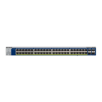
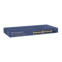
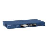
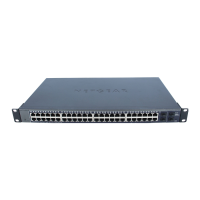
24-Port and 48-Port Gigabit PoE+ Smart Managed Pro Switches with 4 SFP Ports
 Loading...