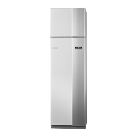
Dimensions and pipe connec-
tions
620
600
560
70
1475
725*
725*
25-50
25
55
130
460
535
405
440
;/ ;/ ;/;/ ;/
Pipe dimensions
12
kW
5-8
kW
Connection
28(mm)(XL6)/(XL7) Brine in/out ext Ø
2822(mm)(XL1)/(XL2) Heating medium
flow/return ext Ø
2822(mm)(XL9) Connection, hot water heater
ext Ø
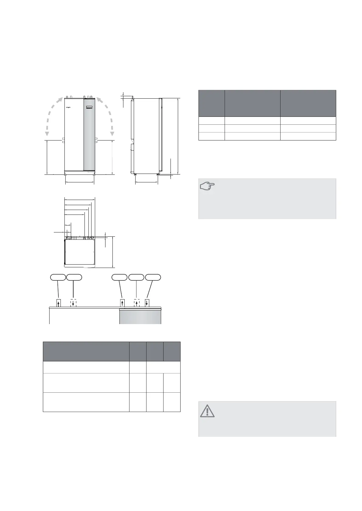
Brine side
Collector
Rock heat, recom-
mended active
drilling depth (m)
Surface soil heat,
recommended col-
lector length (m)
Type
70-90200-3005kW
120-145325-2x2508kW
180-2102x250-2x35012 kW
Applies to PEM hose 40x2.4 PN 6.3.
These are rough example values. At installation the correct
calculations must be made according to local conditions.
Caution
The length of the collector hose varies depend-
ing on the rock/soil conditions, climate zone and
on the climate system (radiators or underfloor
heating).
Max length per coil for the collector should not exceed
400 m.
In those cases where it is necessary to have several collect-
ors, these should be connected in parallel with the pos-
sibility for adjusting the flow of the relevant coil.
For surface soil heat, the hose should be buried at a depth
determined by local conditions and the distance between
the hoses should be at least 1 metre.
For several bore holes, the distance between the holes
must be determined according to local conditions.
Ensure the collector hose rises constantly towards the
heat pump to avoid air pockets. If this is not possible,
airvents should be used.
As the temperature of brine system can fall below 0 °C
it must be protected against freezing down to -15 °C. 1
litre of ready mixed brine per meter of collector hose
(applies when using PEM-hose 40x 2.4 PN 6.3) is used as
a guide value when making the volume calculation.
Anti freeze must be mixed according to manufacturer's
instructions to ensure frost protection and should be
checked using a refractometer.
NOTE
Ensure that cleaning agent has been removed
from the entire system before the anti-freeze is
added.
NIBE Energy Systems Limited recommends water treat-
ments (supplied by e.g. Fernox and Sentinel) specifically
designed for heat pumps.
* Can be angled for side connection.
NIBE™ F1145Chapter 4 | Pipe connections12
 Loading...