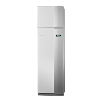
Basic values for the automatic heating control
The values stated on the map apply for the "heating
curve“ in menu 1.9.1.
႑
The first value applies for low temperature* radiator
systems. "temperature" (heating curve offset) in menu
1.1 must be set to -2.
႑
The value in brackets refers to under floor heating
systems** installed in concrete floor structures.
႑
When the system is installed in a timber floor structure
you can use the number before the brackets, but this
value must be reduced by two units. "temperature"
(heating curve offset) in menu 1.1, set in these cases
to -1.
Caution
The map values are usually a good starting point
and concern an approximate room temperature
of 20 °C. The values can be adjusted later if ne-
cessary.
Examples of basic values selection:
႑
House with low temperature* radiator system
London = Area 15 (8).
Set 15 in menu 1.9.1, "heating curve" and -2 in menu
1.1 "temperature" (heating curve offset).
႑
House with under floor heating** installed in a con-
crete floor structure
London = Area 15 (8).
Set 8 in menu 1.9.1, "heating curve" and -2 in menu
1.1 "temperature" (heating curve offset).
႑
Houses with under floor heating** installed in a tim-
ber floor structure
London = Area 15 (8).
Set 13 (see third point in the list above) in menu 1.9.1,
"heating curve" and -1 in menu 1.1 "temperature"
(heating curve offset).
Caution
An increase in the room temperature can be
slowed by the thermostats for the radiators or
under floor heating. Therefore, open the thermo-
stat valves fully, except in those rooms where a
cooler temperature is required, e.g. bedrooms.
A low temperature radiator system refers to a system
where the flow temperature needs to be 55 °C on the
coldest day.
** Under floor heating can be dimensioned very differ-
ently. The example above refers to a system where the
flow temperature must be approx 35-40 °C resp. 45-50
°C on the coldest day.
London
Bristol
Plymouth
Birmingham
Liverpool
Manchester
Glasgow
Edinburgh
Aberdeen
Londonderry
Belfast
Dublin
Cork
Limerick
14 (7)
15 (7)
15 (7)
15 (8)
15 (7)
15 (7)
15 (8
15 (8)
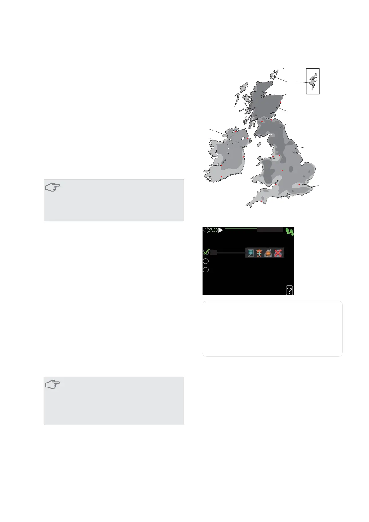
27 Setting operating mode
VWDUW JXLGH
DXWR
PDQXDO
DGG KHDW RQO\
RS PRGH
op. mode
Setting range: auto, manual, add. heat only
Default value: auto
functions
Setting range: compressor, addition, heating, cooling
The heat pump operating mode is usually set to "auto".
It is also possible to set the heat pump to "add. heat
only", but only when an addition is used, or "manual"
and select yourself what functions are to be permitted.
Change the operating mode by marking the desired mode
and pressing the OK button. When an operating mode
is selected it shows what in the heat pump is permitted
(crossed out = not permitted) and selectable alternatives
to the right. To select selectable functions that are permit-
ted or not you mark the function using the control knob
and press the OK button.
Operating mode auto
In this operating mode you cannot select which functions
are to be permitted because it is handled automatically
by the heat pump.
NIBE™ F1145Chapter 6 | Commissioning and adjusting34
 Loading...