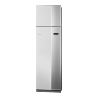
Cable lock
Use a suitable tool to release/lock cables in the heat pump
terminal blocks.
2
1
2
3
LEK
3
4
1
2
$OW
$OW
Connections
NOTE
To prevent interference, unscreened communic-
ation and/or sensor to external connections
cables must not be laid closer than 20 cm to
high voltage cable when cable routing.
Power connection
F1145 must be installed via an isolator switch with a
minimum breaking gap of 3mm. Minimum cable area
must be dimensioned according to the fuse rating used.
Supplied cable for incoming electricity is connected to
terminal block X1 on the immersion heater card (AA1).
$$;
Connection 1x230V
$$;
PE1
0L11PEN
NOTE
F1145-12 contains scroll compressor, which
means that it is important that electrical connec-
tions are made with the correct phase sequence.
With the incorrect phase sequence, the com-
pressor does not start and an alarm is displayed.
If separate supply to the compressor and immersion
heater is required, see section "Switch for external
blocking of addition and/or compressor" on page 22.
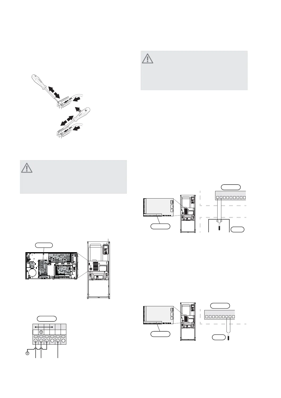
Outside sensor
Install the outside temperature sensor (BT1) in the shade
on a wall facing north or north-west, so it is unaffected
by the
morning sun.
Connect the sensor to terminal block X6:1 and X6:2 on
the input card (AA3). Use a 2 core cable of at least 0.5
mm² cable area.
If a conduit is used it must be sealed to prevent condens-
ation in the sensor capsule.
12
345
67
89
F1245
Externt
$$;
%7
2XWVLGH
VHQVRU
)
$$;
Temperature sensor, hot water charging
The temperature sensor, hot water charging (BT6) is
placed in the submerged tube on the water heater.
Connect the sensor to terminal block X6:7 and X6:8 on
the input card (AA3). Use a 2 core cable of at least 0.5
mm² cable area.
Hot water charging is activated in menu 5.2 or in the
start guide.
123456789
F1245
$$;
%7
)
$$;
19Chapter 5 | Electrical connectionsNIBE™ F1145
 Loading...