Optional connections
External connection options
F1145 has software controlled inputs and outputs on the
input card (AA3), for connecting the extern switch func-
tion or sensor. This means that when an external switch
function or sensor is connected to one of six special
connections, the correct function must be selected to the
correct connection in the software in F1145.
Caution
If an external switch function or sensor is connec-
ted to F1145, the function to use input or output
must be selected in menu 5.4, see page 61.
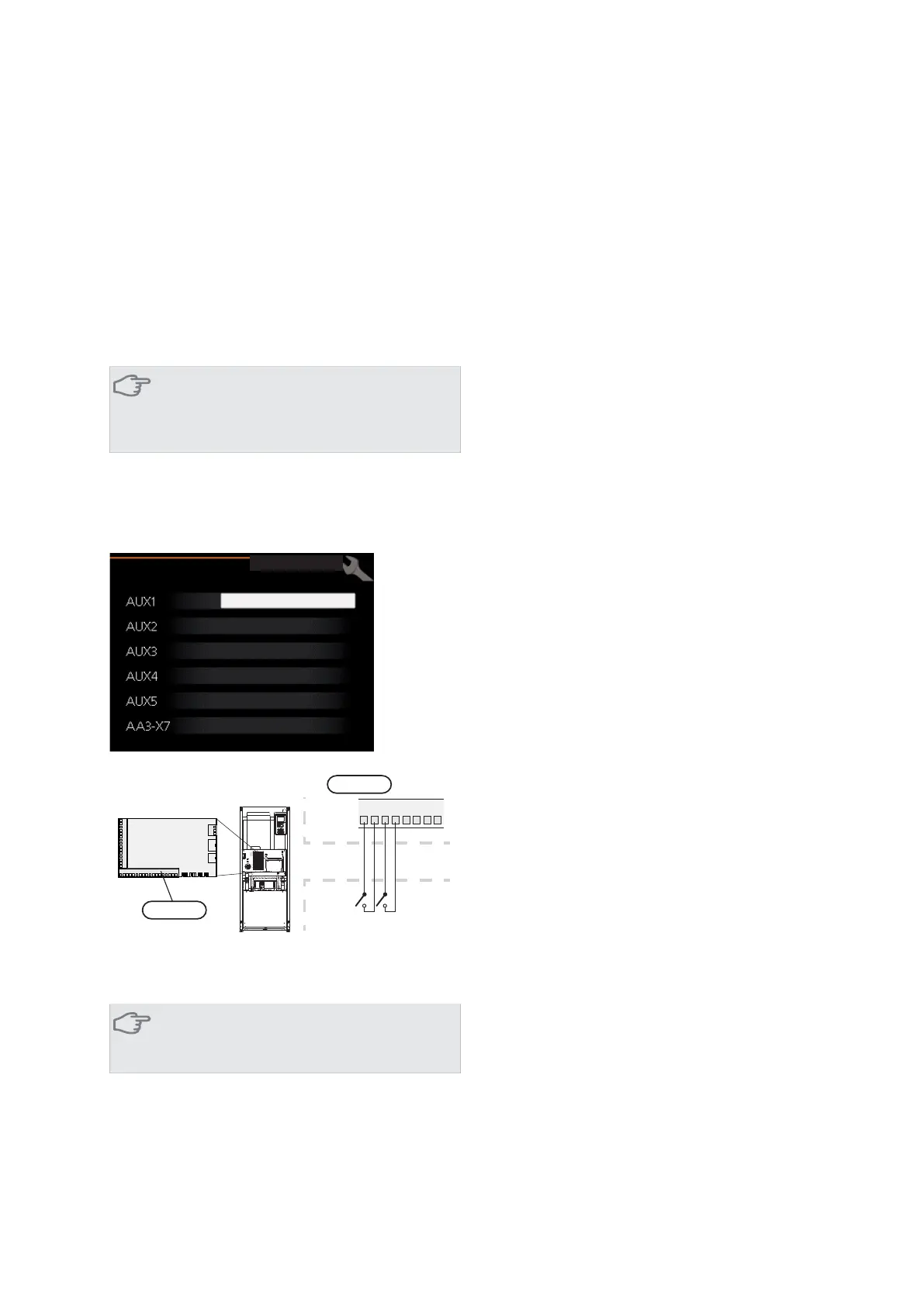
Selectable inputs on the input card for these functions
are AUX1 (X6:9-10), AUX2 (X6:11-12), AUX3 (X6:13-14),
AUX4 (X6:15-16) and AUX5 (X6:17-18). Selectable out-
puts are AA3:X7.
EORFN KHDWLQJ
DFWLYDWH WHPS OX[
QRW XVHG
QRW XVHG
QRW XVHG
DODUP RXWSXW
VRIW LQRXWSXWV
F1245
Externt
91011
121314
15
16
B
A
$$;
([WHUQDO
)
$$;
The example above uses the inputs AUX1 (X6:9-10) andAUX2
(X6:11-12) on the input circuit board (AA3).
Caution
Some of the following functions can also be ac-
tivated and scheduled via menu settings.
Possible selection for AUX inputs
Temperature sensor, hot water top
A temperature sensor for hot water top can be connected
to F1145 for showing the water temperature at the top
of the tank.
The temperature sensor, hot water top (BT7) is connected
to the selected input (menu 5.4, see page 61) on terminal
block X6 on the input card (AA3) which is located behind
the front cover and in a submerged tube on the water
heater.
Use a 2 core cable of at least 0.5 mm² cable area.
Switch for external blocking of addition and/or
compressor
In those cases external blocking of addition and/or com-
pressor is wanted, this can be connected to terminal block
X6 on the input card (AA3), which is positioned behind
the front cover.
The additional heat and/or the compressor are disconnec-
ted by connecting a potential free switch function to the
input selected in menu 5.4, see page 61.
External blocking of addition and compressor can be
combined.
A closed contact results in the electrical output being
disconnected.
Switch for external blocking of heating
In those cases external blocking of heat is used, this can
be connected to terminal block X6 on the input card
(AA3), which is positioned behind the front cover.
Heating operation is disconnected by connecting a poten-
tial free switch function to the input selected in menu
5.4, see page 61.
A closed switch results in blocked heating operation.
Switch for external forced control of brine pump
In those cases external forced control of brine pump is
used, this can be connected to terminal block X6 on the
input card (AA3), which is positioned behind the front
cover.
The brine pump can be force controlled by connecting a
potential free switch function to the input selected in
menu 5.4, see page 61.
A closed switch means that the brine pump is active.
Contact for activation of “temporary lux"
An external contact function can be connected to F1145
for activation of the hot water function“temporary lux".
The switch must be potential free and connected to the
selected input (menu 5.4, see page 61) on terminal block
X6 on the input circuit board (AA3).
"temporary lux" is activated for the time that the contact
is connected.
Contact for activation of “external adjustment"
An external contact function can be connected to F1145
to change the supply temperature and the room temper-
ature.
NIBE™ F1145Chapter 5 | Electrical connections22
 Loading...