Side connection
It is possible to angle the brine connections, for connec-
tion to the side instead of top connection.
To angle out a connection:
1.
Disconnect the pipe at the top connection.
2.
Angle the pipe in the desired direction.
3.
If necessary, cut the pipe to the desired length.
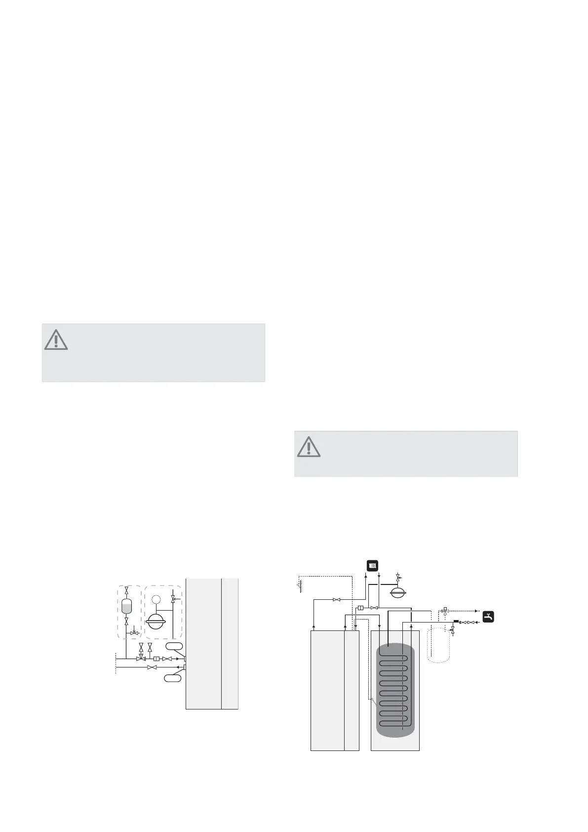
Connecting the brine side
႑
Insulate all indoor brine pipes against condensation.
႑
The level vessel must be installed as the highest point
in the brine system on the incoming pipe before the
brine pump (Alt. 1).
If the level vessel cannot be placed at the highest point
an expansion vessel must be used (Alt. 2).
NOTE
Note that condensation may drip from the level
vessel. Position the vessel so that this does not
harm other equipment.
႑
Details of the antifreeze used must be shown on the
level vessel.
႑
Install the supplied safety valve under the level vessel
as illustrated. The entire length of the overflow water
pipe from the safety valves must be inclined to prevent
water pockets and must also be frost proof.
႑
Install shut off valves as close to the heat pump as
possible.
႑
Fit the supplied particle filter on the incoming pipe.
In the case of connection to an open groundwater system,
an intermediate frost-protected circuit must be provided,
because of the risk of dirt and freezing in the evaporator.
This requires an extra heat exchanger.
P
;/
;/
&ROOHFWRU
$OW $OW
Heating medium side
Connecting the climate system
A climate system is a system that regulates indoor comfort
with the help of the control system in F1145 and for ex-
ample radiators, underfloor heating/cooling, fan con-
vectors etc.
႑
Install all required safety devices, shut-off valves (as
close to the heat pump as possible), and supplied
particle filter.
႑
The safety valve must have a maximum 0.25 MPa (2.5
bar) opening pressure and be installed on the heating
medium return as illustrated. The entire length of the
overflow water pipe from the safety valves must be
inclined to prevent water pockets and must also be
frost proof.
႑
When connecting to a system with thermostats on
all radiators, a relief valve must be fitted, or some of
the thermostats must be removed to ensure sufficient
flow.
Before installing the heat pump in an existing system, it
is important that the system is properly flushed through.
Even if the heat pump is to be installed in a new system,
the heat pump and system should be flushed.
NOTE
Ensure that cleaning agent has been removed
from the entire system before adding inhibitor.
After flushing an inhibitor should be used for long-term
anti-corrosion protection.
NIBE Energy Systems Limited recommends water treat-
ments (supplied by e.g. Fernox and Sentinel) specifically
designed for heat pumps.
T
13Chapter 4 | Pipe connectionsNIBE™ F1145
 Loading...