General
Pipe installation must be carried out in accordance with
current norms and directives. F1226 can operate with a
return temperature of up to 56 °C and an outgoing
temperature from the heat pump of 70 (63 °C with only
the compressor).
F1226 is not equipped with external shut off valves; these
must be installed to facilitate any future servicing.
Caution
Ensure that incoming water is clean. When using
a private well, it may be necessary to supple-
ment with an extra water filter.
Caution
Any high points in the climate system, must be
equipped with air vents.
NOTE
The pipe system needs to be flushed out before
the heat pump is connected so that debris can-
not damage component parts.
Symbol key
MeaningSymbol
Venting valve
Shut-off valve
Non-return valve
Level vessel
Trim valve
Shunt / shuttle valve
Safety valve
Temperature sensor
Expansion vessel
Pressure gauge
Circulation pump
Particle filter
Auxiliary relay
Compressor
Heat exchanger
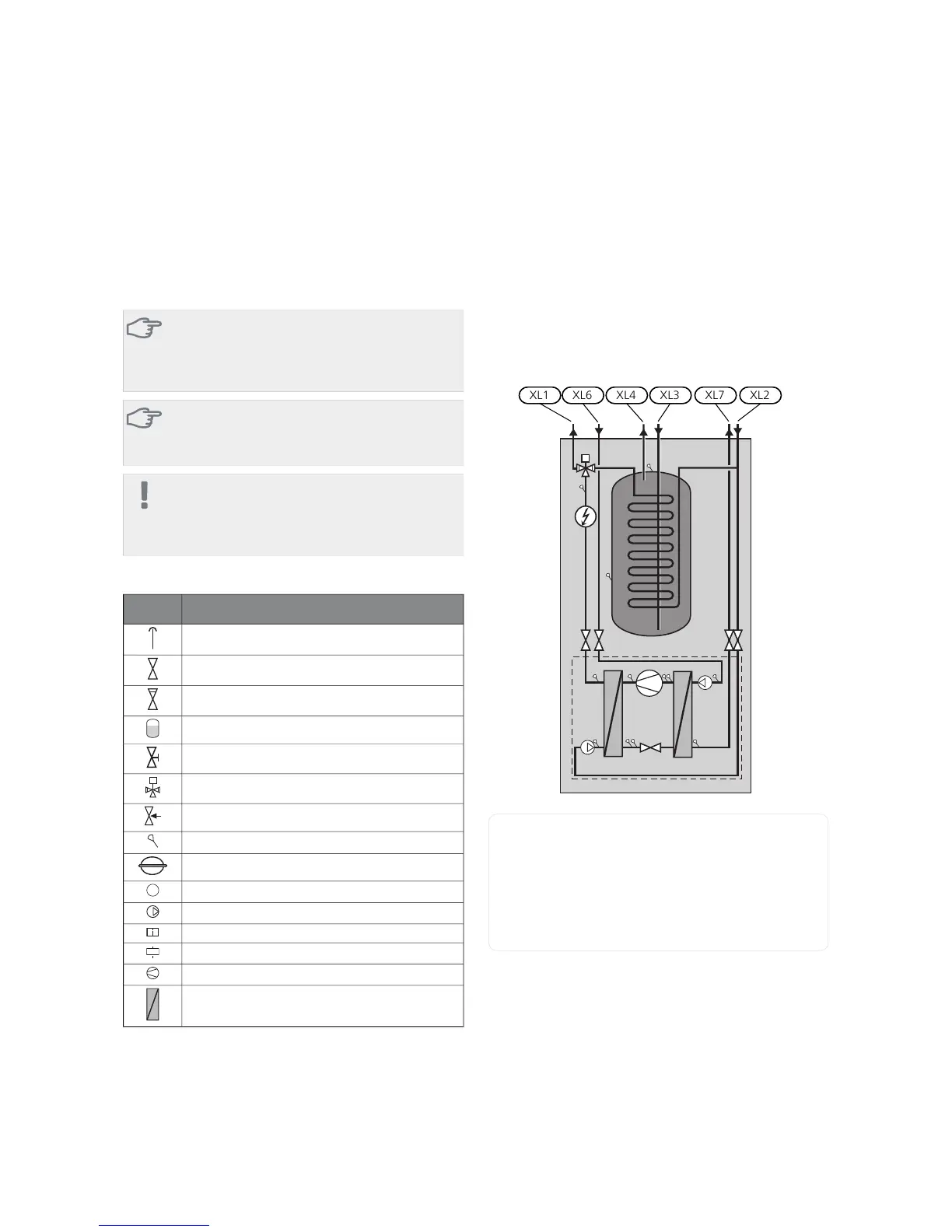
System diagram
F1226 consists of a heat pump, water heater, electrical
module, circulation pumps and a control system. F1226
is connected to the brine and heating medium circuits.
In the heat pump evaporator, the brine (water mixed
with anti-freeze, glycol or ethanol) releases its energy to
the refrigerant, which is vaporised in order to be com-
pressed in the compressor. The refrigerant, of which the
temperature has now been raised, is passed to the con-
denser where it gives off its energy to the heating medi-
um circuit and, if necessary, to the water heater. If there
is a greater need for heating/hot water than the com-
pressor can provide there is an integrated immersion
heater.
Connection, heating medium flowXL1
Connection, heating medium returnXL2
Connection, cold waterXL3
Connection, hot waterXL4
Connection, brine inXL6
Connection, brine outXL7
13Chapter 4 | Pipe connectionsNIBE F1226
4 Pipe connections
 Loading...


