General
All electrical equipment except for the outdoor temper-
ature sensors has been connected at the factory.
■
Disconnect the heat pump before insulation testing
the house wiring.
■
If the building is equipped with an earth-fault breaker,
F1226 should be equipped with a separate one.
■
If a miniature circuit breaker is used this should have
at least motor characteristic “C”. See page 49 for fuse
size.
■
Electrical wiring diagram for the heat pump, see page
57.
■
Communication and sensor cables to external connec-
tions must not be laid close to high current cables.
■
The minimum area of communication and sensor
cables to external connections must be 0.5 mm² up to
50 m, for example EKKX or LiYY or equivalent.
■
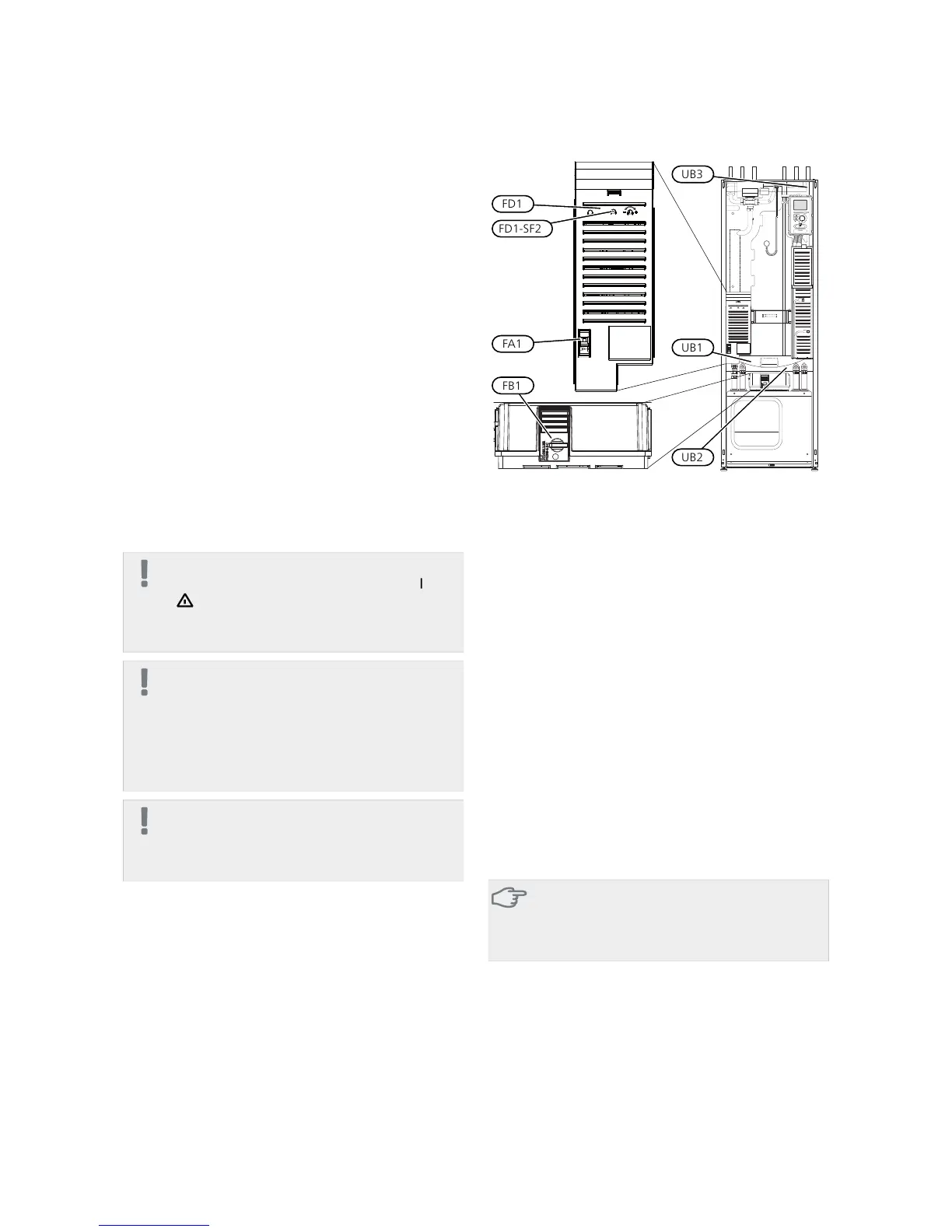
When cable routing in F1226, cable grommets (e.g.
UB1-UB3, marked in image) must be used. In UB1-UB3
the cables are inserted through the heat pump from
the back to the front.
NOTE
The switch (SF1) must not be moved to "" or
" " until the boiler has been filled with water.
Component parts of the product can be dam-
aged.
NOTE
Electrical installation and service must be carried
out under the supervision of a qualified electri-
cian. Cut the current with the circuit breaker
before carrying out any servicing. Electrical in-
stallation and wiring must be carried out in ac-
cordance with the stipulations in force.
NOTE
Check the connections, main voltage and phase
voltage before the machine is started, to prevent
damage to the heat pump electronics.
Miniature circuit-breaker
The heat pump operating circuit and some of its internal
components are internally fused by a miniature circuit
breaker (FA1).
Temperature limiter
The temperature limiter (FD1) cuts the power to the
electric additional heat if the temperature exceeds 89°C
and is reset manually.
Resetting
The temperature limiter (FD1) is accessible behind the
front cover. Reset the temperature limiter by pressing
the button (FD1-SF2) using a small screwdriver.
Motor cut-out
Motor protection breaker (FB1) cuts the power to the
compressor if the current is too high.
Resetting
The motor protection breaker (FB1) is accessible behind
the front cover. The breaker is reset by twisting the con-
trol knob to horizontal position.
Caution
Check the miniature circuit-breaker, temperat-
ure limiter and motor protection breaker. They
may have tripped during transportation.
NIBE F1226Chapter 5 | Electrical connections18
5 Electrical connections
 Loading...


