3x400V (maximum electrical output, connected upon
delivery 7 kW)
654321kW
onoffoffoffoffoff1
offoffoffonoffoff2
onoffoffonoffoff3
offonoffonoffoff4
onoffoffonoffon5
offonoffonoffon6
ononoffonoffon7
3x400V (maximum electrical output, switched to 9
kW)
654321kW
offonoffoffoffoff2
offonoffonoffoff4
offonoffonoffon6
ononononoffon9
3x400V
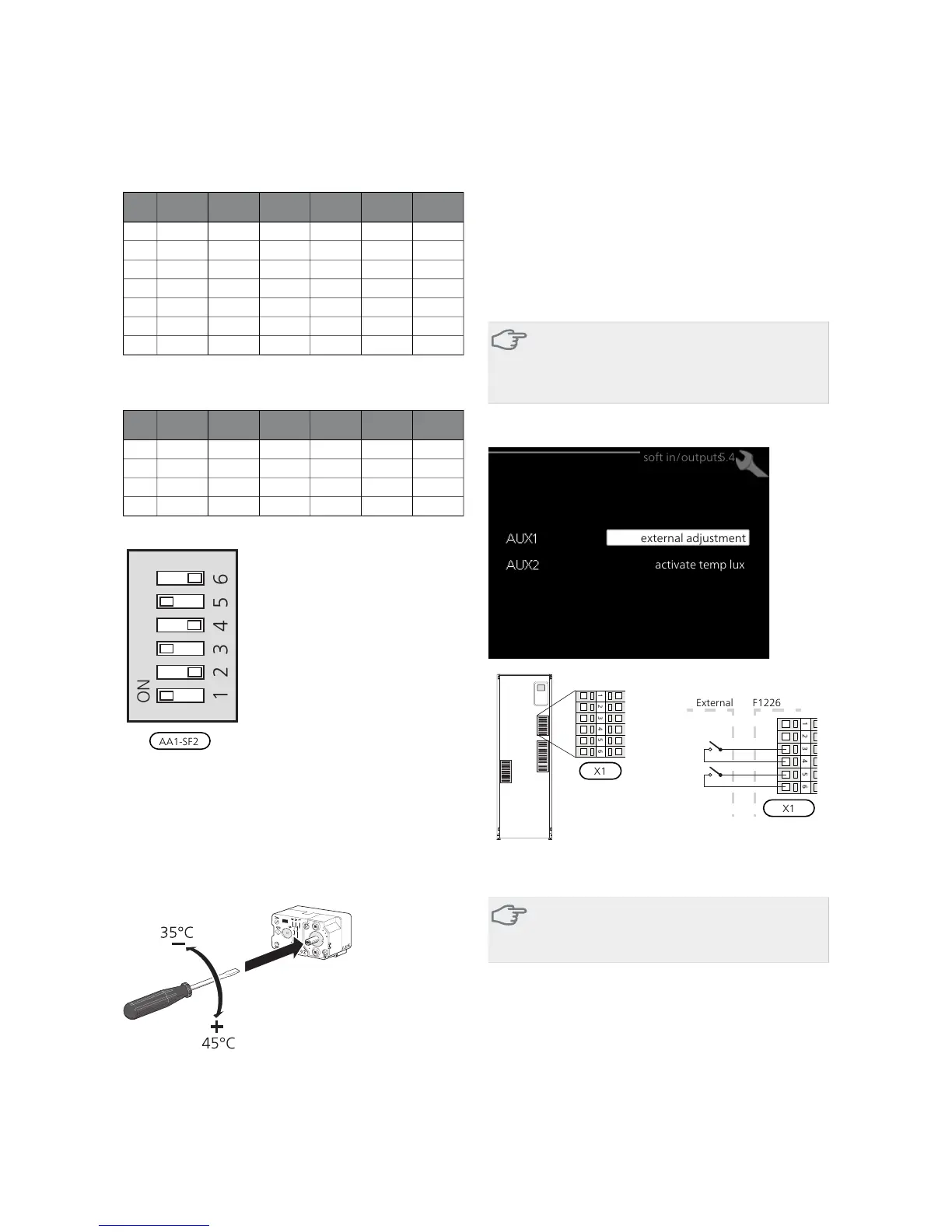
The image shows the dip-switch (AA1-SF2) in the factory
setting, that is 6 kW.
Emergency mode thermostat
The supply temperature in emergency mode is set using
a thermostat (FD1-BT30). It can be set to 35 (pre-set, for
example under floor heating) or 45 °C (for example radi-
ators).
LEK
LEK
För markvärme!
För frånluftsvärme!
Optional connections
External connection options
On the terminal block (X1) F1226 has software controlled
inputs for connecting the external switch function or
sensor. This means that when an external switch function
or sensor is connected to one of two special connections,
the correct function must be selected to the correct
connection in the software in F1226.
Caution
If an external switch function or sensor is con-
nected to F1226, the function for use input must
be selected in menu 5.4, see page 37.
Selectable inputs on the input card for these functions
are AUX1 (X1:3-4) and AUX2 (X1:5-6)
external adjustment
activate temp lux
soft in/outputs5.4
The example above uses the inputs AUX1 (X1:3-4) and AUX2 (X1:5-
6) on the terminal block (X1).
Caution
Some of the following functions can also be ac-
tivated via menu settings.
Possible selection for AUX inputs
Room temperature sensor (accessory)
F1226 can be supplemented with the accessory RTS 40
(room temperature sensor).
The room temperature sensor is connected to the selec-
ted input (menu 5.4, see page 37) on terminal block X1
and installed in the building according to the installer
handbook.
NIBE F1226Chapter 5 | Electrical connections22
 Loading...


