Post adjustment and venting
Pump adjustment
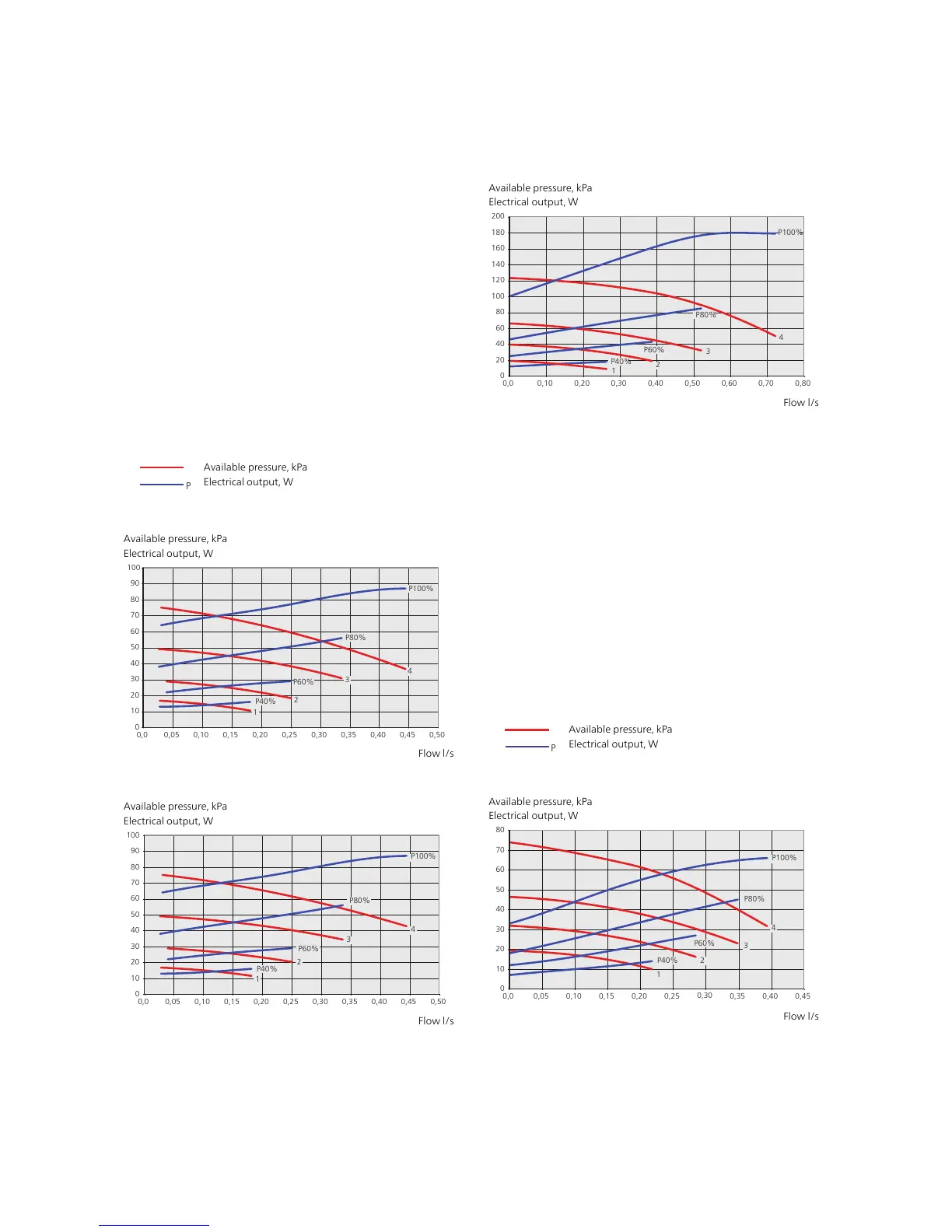
Brine side
To set the correct flow in the brine system the correct
speed must be set for the brine pump.
Adjust the flow so that the temperature difference
between brine out (BT11) and brine in (BT10) is between
2 - 5 °C when the system has come into balance (ideally
five minutes after compressor start). Check these temper-
atures in menu 3.1 “service info” and adjust the brine
pump (GP2) speed until the temperature difference is
obtained. A high difference indicates a low brine flow
and a low difference indicates a high brine flow.
Read off what speed the brine pump should have from
the diagrams below.
0
20
40
60
80
100
120
140
160
180
200
0 0,2 0,4 0,6 0,8 1 1,2
0
20
40
60
80
100
120
140
160
180
200
0 0,10 0,20 0,30 0,40 0,50 0,60
0
20
40
60
80
100
120
140
160
180
200
0
0,1 0,2 0,3 0,4 0,5 0,6 0,7 0,8 0,9 1
0
10
20
30
40
50
60
70
80
90
100
0 0,05 0,10 0,15 0,20 0,25 0,30 0,35 0,40 0,45 0,50
0
10
20
30
40
50
60
70
80
90
100
0 0,05 0,10 0,15 0,20 0,25 0,30 0,35 0,40 0,45 0,50
0
10
20
30
40
50
60
70
80
90
100
0 0,05 0,10 0,15 0,20 0,25 0,30 0,35 0,40 0,45 0,50
Tillgängligt tryck, kPa / Eleffekt, W
Eleffekt
Tillgängligt tryck
Flöde
l/s
P
P100%
100%
P80%
80%
P60%
60%
P40%
40%
Tillgängligt tryck, kPa / Eleffekt, W
Eleffekt
Tillgängligt tryck
Flöde
l/s
P
Tillgängligt tryck, kPa / Eleffekt, W
Eleffekt
Tillgängligt tryck
Flöde
l/s
P
Eleffekt, W
Tillgängligt tryck, kPa
Eleffekt
Tillgängligt tryck
Flöde
l/s
P
P100%
P90%
P70%
P50%
100%
90%
70%
50%
Eleffekt, W
Tillgängligt tryck, kPa
Eleffekt
Tillgängligt tryck
Flöde
l/s
P
P100%
P90%
P80%
P70%
P60%
100%
90%
60%
70%
80%
Eleffekt, W
Tillgängligt tryck, kPa
Eleffekt
Tillgängligt tryck
Flöde
l/s
P
P100%
P80%
P60%
100%
60%
80%
F114
5/F1245 5kW
F1145/F1245 6kW
F1145/F1245 8kW
F1145/F1245 10kW
F1145/F1245 12kW
F1145/F1245 15 & 17kW
P100%
100%
P80%
80%
P60%
60%
P40%
40%
P100%
100%
P80%
80%
P60%
60%
P40%
40%
Available pressure, kPa
Electrical output, W
1
2
3
4
P40%
P60%
P80%
P100%
Pumpkapacitet, köldbärarsida för F1126/F1226 5-6kW.
Eleffekt, W
Tillgängligt tryck, kPa
10
0
30
60
50
40
20
70
80
90
100
Flöde l/s
0,0 0,05 0,10 0,15 0,20 0,25 0,30 0,35 0,40 0,45 0,50
Available pressure, kPa
Electrical output, W
Flow l/s
0,0 0,05
0,10
0,15 0,20 0,25 0,30 0,35 0,40 0,45 0,50
P40%
P60%
P80%
P100%
1
2
3
4
Pumpkapacitet, köldbärarsida för F1126/F1226 8 kW.
Eleffekt, W
Tillgängligt tryck, kPa
Flöde l/s
10
0
30
100
40
50
60
70
80
90
20
Available pressure, kPa
Electrical output, W
Flow l/s
P40%
P60%
P80%
P100%
1
2
3
4
Pumpkapacitet, köldbärarsida för F1126/F1226 11-12kW.
Eleffekt, W
Tillgängligt tryck, kPa
Flöde l/s
0,0 0,10 0,20 0,30 0,40 0,50 0,60 0,70 0,80
20
0
60
120
100
80
40
140
160
180
200
Available pressure, kPa
Electrical output, W
Flow l/s
Heating medium side
To set the correct flow in the climate system the correct
speed must be set for the heating medium pump in the
different operating conditions.
The flow must have a temperature difference suitable
for the operating case (heating operation: 5 - 10 °C, hot
water generation: 5 - 9 °C) between supply temperature
(BT2) and return temperature (BT3). Check these temper-
atures in menu 3.1 “service info” and adjust the heating
medium pump (GP1) speed until the temperature differ-
ence is attained. A high difference indicates a low heat-
ing medium supply and a low difference indicates a high
heating medium supply.
Set the speed of the heating medium pump in the menu
5.1.11, see page 37.
Read off what speed the heating medium pump should
be from the diagrams below.
0
20
40
60
80
100
120
140
160
180
200
0 0,2 0,4 0,6 0,8 1 1,2
0
20
40
60
80
100
120
140
160
180
200
0 0,10 0,20 0,30 0,40 0,50 0,60
0
20
40
60
80
100
120
140
160
180
200
0
0,1 0,2 0,3 0,4 0,5 0,6 0,7 0,8 0,9 1
0
10
20
30
40
50
60
70
80
90
100
0 0,05 0,10 0,15 0,20 0,25 0,30 0,35 0,40 0,45 0,50
0
10
20
30
40
50
60
70
80
90
100
0 0,05 0,10 0,15 0,20 0,25 0,30 0,35 0,40 0,45 0,50
0
10
20
30
40
50
60
70
80
90
100
0 0,05 0,10 0,15 0,20 0,25 0,30 0,35 0,40 0,45 0,50
Tillgängligt tryck, kPa / Eleffekt, W
Eleffekt
Tillgängligt tryck
Flöde
l/s
P
P100%
100%
P80%
80%
P60%
60%
P40%
40%
Tillgängligt tryck, kPa / Eleffekt, W
Eleffekt
Tillgängligt tryck
Flöde
l/s
P
Tillgängligt tryck, kPa / Eleffekt, W
Eleffekt
Tillgängligt tryck
Flöde
l/s
P
Eleffekt, W
Tillgängligt tryck, kPa
Eleffekt
Tillgängligt tryck
Flöde
l/s
P
P100%
P90%
P70%
P50%
100%
90%
70%
50%
Eleffekt, W
Tillgängligt tryck, kPa
Eleffekt
Tillgängligt tryck
Flöde
l/s
P
P100%
P90%
P80%
P70%
P60%
100%
90%
60%
70%
80%
Eleffekt, W
Tillgängligt tryck, kPa
Eleffekt
Tillgängligt tryck
Flöde
l/s
P
P100%
P80%
P60%
100%
60%
80%
F114
5/F1245 5kW
F1145/F1245 6kW
F1145/F1245 8kW
F1145/F1245 10kW
F1145/F1245 12kW
F1145/F1245 15 & 17kW
P100%
100%
P80%
80%
P60%
60%
P40%
40%
P100%
100%
P80%
80%
P60%
60%
P40%
40%
Available pressure, kPa
Electrical output, W
0,0 0,05 0,10 0,15 0,20 0,25
0,30
0,35 0,40 0,45
P40%
P60%
P80%
P100%
1
2
3
4
Pumpkapacitet, värmebärarsida för F1126/F1226 5-6 kW.
Eleffekt, W
Tillgängligt tryck, kPa
Flöde l/s
10
0
30
40
50
60
70
80
20
Available pressure, kPa
Electrical output, W
Flow l/s
27Chapter 6 | Commissioning and adjustingNIBE F1226
 Loading...


