Connect the sensor(s) to
terminal block X1 according
to the instructions below.
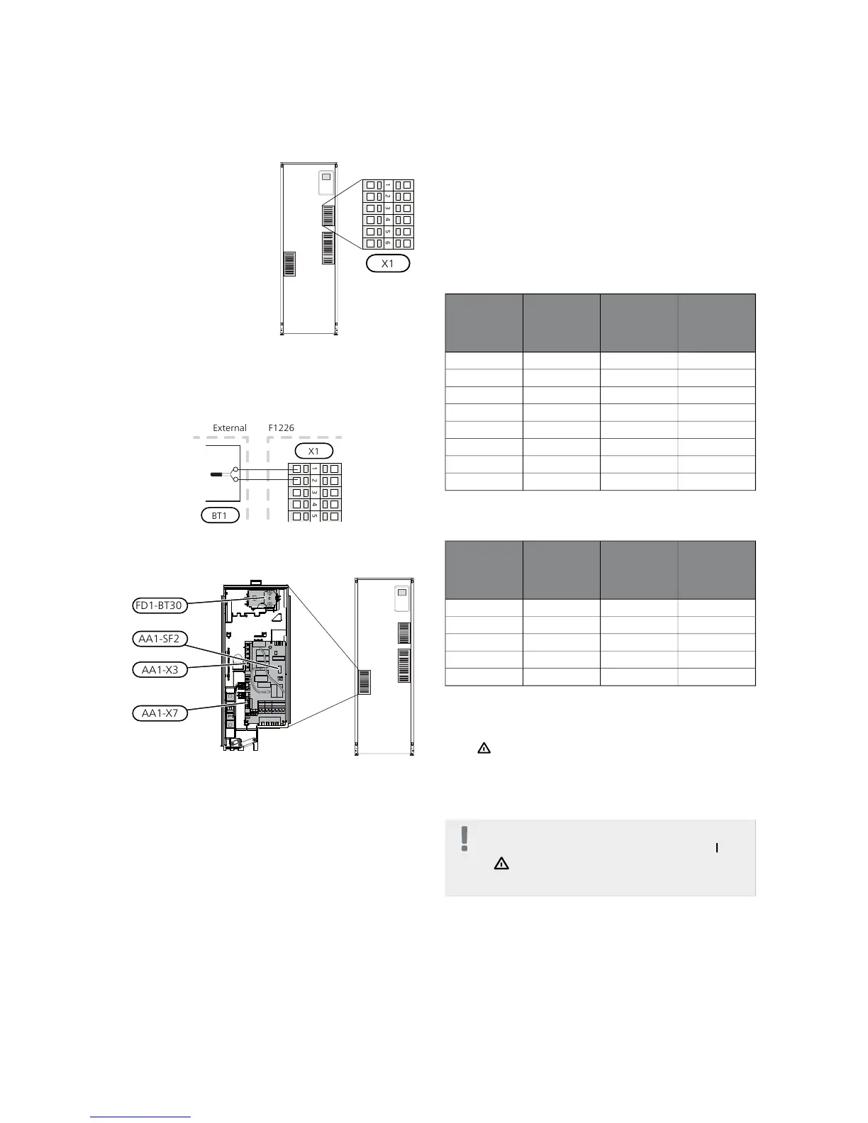
Outside sensor
Install the outdoor temper-
ature sensor (BT1) in the
shade on a wall facing north
or north-west, so it is unaf-
fected by the morning sun
for example.
Connect the sensor to ter-
minal block X1:1 and X1:2.
Use a twin core cable of at least 0.5 mm² cable area.
If a conduit is used it must be sealed to prevent condens-
ation in the sensor capsule.
Electrical addition - maximum output
The electric additional heat may be restricted depending
on the selected country.
On delivery, the immersion heater is connected for a
maximum of 7 kW (switchable to 9 kW).
The immersion heater's output is split into seven steps
(four steps if the immersion heater is switched to maxim-
um 9 kW), according to the table below.
Setting max electrical output
Setting maximum output in the electric additional heat
is done in menu 5.1.12.
The table displays the total phase current for the immer-
sion heater at start up. If an immersion heater has already
been started and is not used for its full capacity the val-
ues in the table can be changed because the control
initially uses this immersion heater.
Switching to maximum electrical output
If more than the maximum output (7 kW) for the immer-
sion heater connected on delivery is needed, the heat
pump can be switched to maximum 9 kW.
Move the white cable from terminal block X7:23 to ter-
minal block X3:13 (the seal on the terminal block must
be broken) on the immersion heater card (AA1).
3x400V V (maximum electrical output, connected
upon delivery 7 kW)
Max phase
current
L3(A)
Max phase
current
L2(A)
Max phase
current
L1(A)
Max electric-
al addition
(kW)
–––0
4.3––1
–8.7–2
4.38.7–3
8.78.7–4
13.08.78.75
8.78.78.76
13.08.78.77
3x400V (maximum electrical output, switched to 9
kW)
Max phase
current
L3(A)
Max phase
current
L2(A)
Max phase
current
L1(A)
Max electric-
al addition
(kW)
–––0
–8.7–2
8.78.7–4
8.78.78.76
15.615.68.79
Emergency mode
When the heat pump is set to emergency mode (SF1 is
set to ) only the most necessary functions are activated.
■
The compressor is off and heating is managed by the
immersion heater.
■
Hot water is not produced.
NOTE
The switch (SF1) must not be moved to "" or
" " until F1226 has been filled with water.
Components in the product can be damaged.
Power in emergency mode
The immersion heater’s output in emergency mode is
set with the dipswitch (S2) on the immersion heater cir-
cuit board (AA1) according to the table below. Factory
setting is 6 kW.
When installing according to current building regulations
(BBR) the immersion heater's power in emergency mode
must be set to the maximum permitted electrical output.
21Chapter 5 | Electrical connectionsNIBE F1226
 Loading...


