Wheels, Drive System 102Service Manual – SC2000
Drive System Gearmotor Amperage Test
Warning! Thisproceduremustbeperformedbyqualiedpersonnelonlyandwiththehelpof
an assistant.
1. Drive the machine on a level oor.
2. Lift the recovery tank assembly and the driver’s seat.
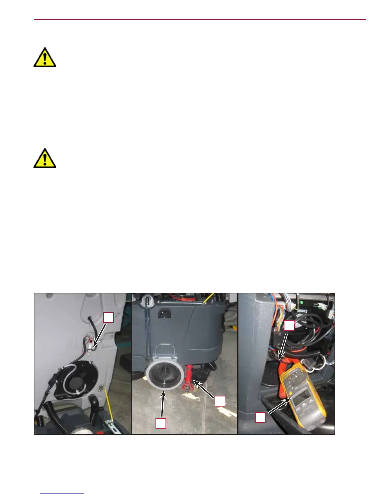
3. Apply a jumper wire (A, Figure 5) on the driver’s seat sensor connector to disable the system.
4. Disassemble the electronic component compartment cover and the function electronic board panel.
5. Place a suitable lifting device (B) to raise one side of the machine approximately 2 cm from the oor (C)
and allow one driving wheel to turn freely.
Warning! Pay attention to the rotation of the driving wheel when performing the following
steps.
6. Apply the amp clamp (D) on one (black) cable (E) of the drive system motor wiring harness.
7. Turn on the machine and drive it at the maximum forward speed by pressing the drive pedal and check
that the amperage is 3 - 7A at 24V.
8. Release the drive pedal.
9. Switch off the machine and remove the amp clamp (D).
10. If the amperage is higher, perform the following procedures to detect and correct the abnormal
amperage:
◦ Check if there is dust or debris preventing the wheel rotation.
◦ If necessary, check the motor carbon brushes;
◦ If necessary, disassemble the motor and check the condition of all its components.
11. If the above-mentioned procedures do not produce the correct readings for the gearmotor amperage, the
gearmotor must be replaced.
Figure 4
C
E
A
B
D
 Loading...


