Squeegee System 87Service Manual – SC2000
Squeegee System
Functional Description
The squeegee system cleans the liquid off the oor, which is then collected by the recovery system.
The squeegee is mounted on castors and the weight of the system presses it down on the oor.
The squeegee is held in place by two quick-t wing nuts in the squeegee support slots. In case of xed ob-
stacles, the quick-t system allows for squeegee immediate removal.
The squeegee support is held on the frame by two tie rods and a centring spring, allowing some lateral move-
ment.
The angle of the squeegee and the correct adherence of the blades on the oor can be adjusted with a knob.
The front blade has an opening in the bottom edge so the squeegee can collect the water on the oor. The
design and the central duct make it easy for the squeegee to clear the water. The rear blade edge is smooth.
All 4 functional edges of each blade can be used before it needs replacing.
The squeegee is lifted and lowered by an actuator (M6) located in the solution tank compartment. It is acti-
vated at the same time as the brush deck.
The squeegee actuator (M6) has 2 limit microswitches (not accessible). Every time it is raised or lowered, the
actuator is activated by the electronic board for 15 seconds. The squeegee must reach the correct limit switch
by the end of this time.
In any case the electronic board cuts off the power supplied to the actuator after 15 seconds, to prevent damag-
ing the actuator.
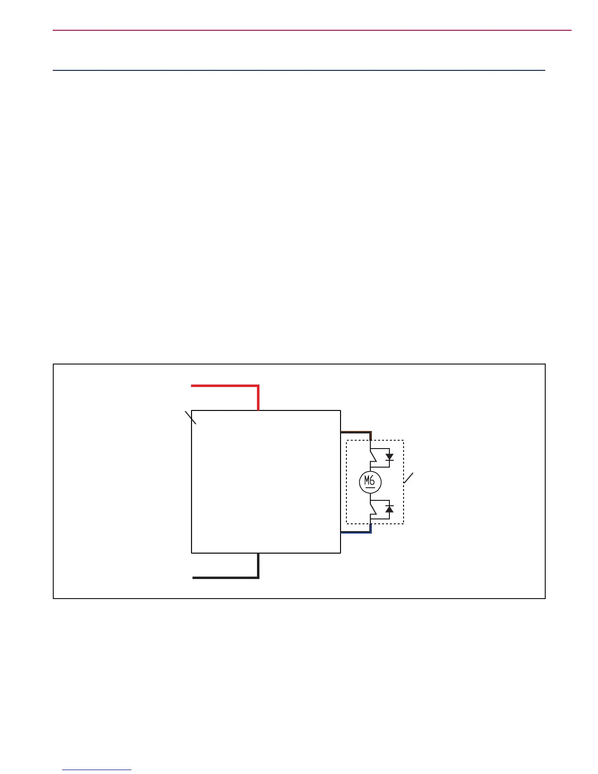
Wiring Diagram
B+
B -
Electronic board power supply +
Electronic board power supply -
FUNCTION
ELECTRONIC
BOARD (EB1)
J3.4
J3.1
Squeegee actuator power supply -/+
Squeegee actuator power supply +/-
SQUEEGEE
ACTUATOR (M6)
Figure 1
 Loading...


