Mounting a Cabinet Installation
NFS-640 Installation Manual P/N 51332:B1 12/01/2003 29
3.3 Mounting a Cabinet
This section provides instructions for mounting an CAB-4 Series backbox to a wall. Follow these
guidelines when mounting the backbox:
• Locate the backbox so that the top edge is 66 inches (1.6764 m) above the surface of the
finished floor.
• Allow sufficient clearance around cabinet for door to swing freely. (See Section 2.3 “System
Cabinets”.)
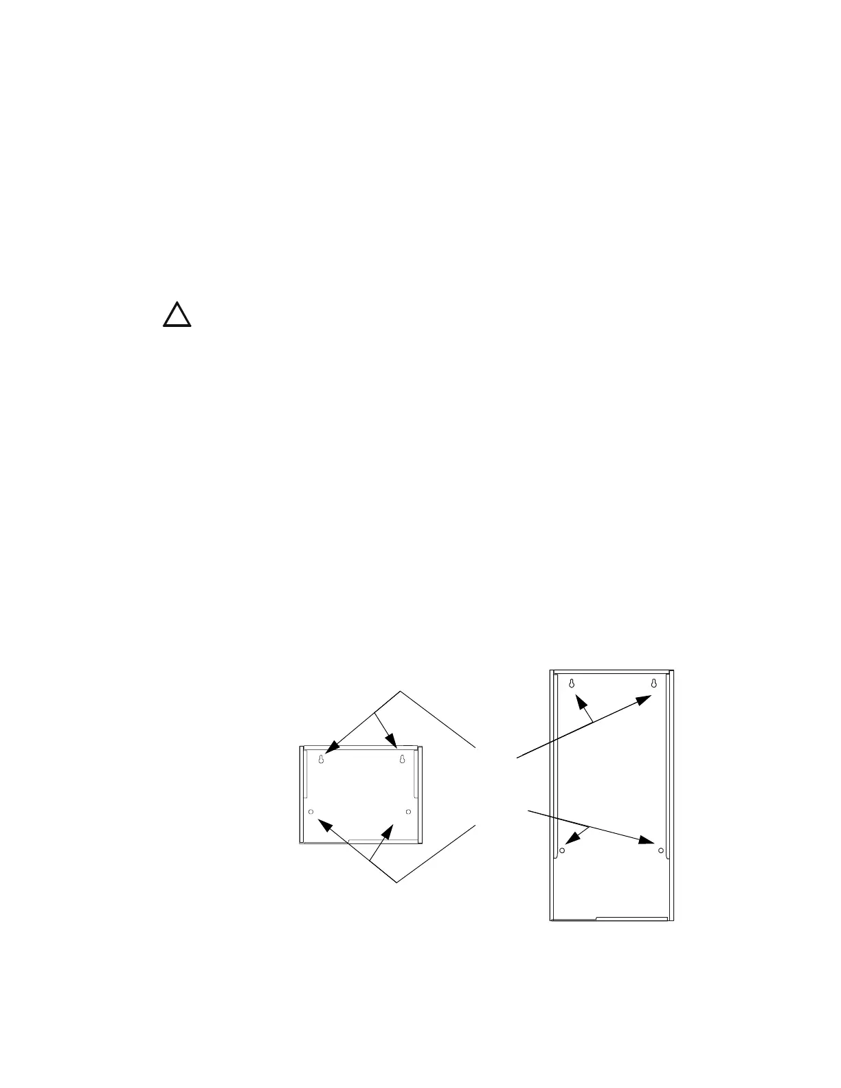
• Use the four holes in the back surface of the backbox to provide secure mounting (See
Figure 5).
• Mount the backbox on a surface that is in a clean, dry, vibration-free area.
Follow the instructions below.
1. Mark and pre-drill holes for the top two keyhole mounting bolts (0.25 inch, 0.635 cm). Use
mounting hardware appropriate for the mounting surfaces; see UL 2017 Pull-Test
Requirements.
2. Select and punch open the appropriate knock-outs. (For selection guidelines, see Section 3.6
“UL Power-limited Wiring Requirements”.)
3. Using the keyholes, mount the backbox over the two screws.
4. Mark the location for the two lower holes, remove the backbox and drill the mounting holes.
5. Mount the backbox over the top two screws, then install the remaining fasteners. Tighten all
fasteners securely.
6. Feed wires through appropriate knockouts.
7. Install control panel and other components according to Section 3.5 “Installing the Control
Panel” before installing hinges and door according to
CAB-3/CAB-4 Series Cabinet Installation
Document.
Figure 5 Mounting Holes of a Backbox
!
CAUTION: Unless you are familiar with the placement of components within this backbox, only
use the knockout locations provided for conduit entry.
Keyholes
2 places
Mounting holes
2 places
CAB-4
Series
Backbox,
A-size (one-
row)
nfs640cabinetmountingholes.cdr
CAB-4
Series
Backbox,
D-size
(four-row)

 Loading...


