Installing Panel Circuit Modules Installation
NFS-640 Installation Manual P/N 51332:B1 12/01/2003 43
3.7 Installing Panel Circuit Modules
3.7.1 Overview
Installation of a panel circuit module is divided into five (5) operations:
• Mounting an optional expander board to the module (e.g. mounting ICE-4 onto an ICM-
4RK).
• Connecting communication ribbon cables from Control Panel to the module.
• Installing the module onto a chassis.
• Connecting modules to the power supply.
• Field wiring the module.
Refer to Section 2.10 “Panel Circuit Modules” for a complete list of modules and their expanders.
3.7.2 Mounting Expander Boards
Expander Board Modules, such as ICE-4 or CRE-4, need to be mounted onto their respective
modules (ICM-4RK, CRM-4RK) prior to installation onto a chassis. To mount an Expander
Module:
1. Remove one module support screw and set it aside for later use.
2. Replace the module support screw with one module stand-off.
3. Repeat Steps 1 and 2 for the three remaining module support screws.
4. Insert pins on the front of the expander board into connector on the back of the module. Make
sure the pins are in line; then, press the two units together until they snap into place.
5. Install the four module support screws (removed earlier) through the back of the expander
board and into the stand-offs. Tighten securely.
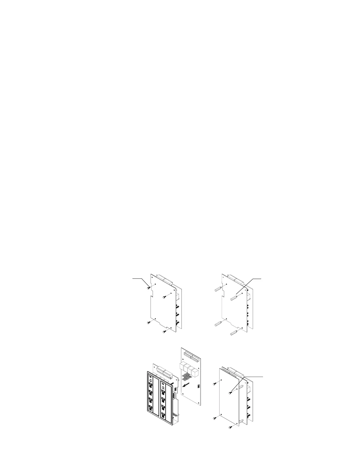
Figure 21 illustrates the steps.
Figure 21 Expander Module Installation
Install module stand-
off
Remove existing
module support
screw
Plug in the expander board
Secure with module
support screws
nfs640-pcmods.cdr
Steps 1 & 2
Steps 4 & 5

 Loading...


