Installing the Control Panel Installation
NFS-640 Installation Manual P/N 51332:B1 12/01/2003 41
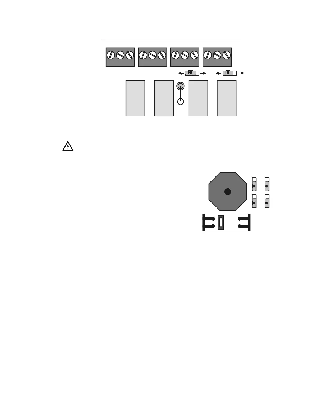
Figure 18 Form-C Relay Connections
3.5.14 Backup-Alarm Switches
Backup alarm switches are provided that enable NACs
and the alarm relay to activate during a backup alarm
condition. If the main board’s microcontroller fails and
an alarm is reported by any detector or a monitor
module that has backup reporting enabled, the NAC
will turn on if the corresponding switch was enabled.
The alarm will activate during microcontroller failure
regardless of the settings of Switch 6-9.
• Switch 6 - NAC#1
• Switch 7 - NAC#2
• Switch 8 - NAC#3
• Switch 9 - NAC#4
So, for example, if Switch 6 and Switch 8 were enabled at the time of an alarm during
microcontroller failure, NAC#1 and NAC#3 would activate. Follow sequence of steps in Section
3.2 “Installation Checklist”, Table 2; this is Step 7.
3.5.15 Installing a Transmitter Module TM-4
TM-4 is power-limited. Connections are on TB7 nonresettable output and TB13 EIA-485 ACS
Mode. Refer to the Transmitter Module TM-4 installation document for installation details.
ALARM RELAY
NO NC C
TROUBLE RELAY
NO NC C
SUPERVISORY RELAY
NO NC C
SECURITY RELAY
NO NC C
TB8
TB9 TB10
TB11
SW1
SW5
SUPV ALARM SECUR ALARM
SW1 set to Supervisory
SW5 set to Security
Move switch to opposite
position to set to Alarm.
nfs640-relay.cdr
!
WARNING: Do not enable the BACKUP option switch for any of the four Notification Appliance
Circuits (NACs) if they are used for releasing functions!
Figure 19 Backup Alarm Switches
SW6
NAC
SW7
ENAB
DISAB
SW8
SW9
13
24
nfs640-sw6-9.cdr

 Loading...


