Installation UL Power-limited Wiring Requirements
42 NFS-640 Installation Manual P/N 51332:B1 12/01/2003
3.6 UL Power-limited Wiring Requirements
Power-limited and nonpower-limited circuit wiring must remain separated in the cabinet. All
power-limited circuit wiring must remain at least 0.25 inches (6.35 mm) from any nonpower-
limited circuit wiring. All power-limited and nonpower-limited circuit wiring must enter and exit
the cabinet through different knockout and or conduits. To maintain separation, group non-power
limited modules together, i.e., group modules on the same side of the enclosure or in separate rows.
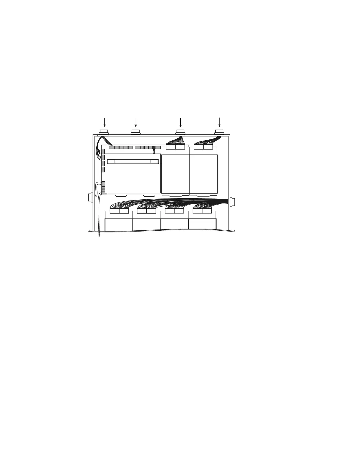
Figure 20 shows one configuration that meets these UL requirements. The first two rows of
modules are configured with at least a 0.25 inch (6.35 mm) separation between power-limited and
nonpower-limited wiring; AC and battery wiring is routed away from power-limited wiring.
Figure 20 Typical Wiring for UL Power-limited Wiring Requirements
Note: AC and battery wiring are not power-limited. Maintain at least 0.25 inches (6.35 mm)
between power-limited and non power-limited circuit wiring. Install tie wraps and adhesive squares
to secure the wiring. Use a power-limited source for relay output on terminals TB8 – TB11.
3.6.1 Labeling Modules and Circuits
At the time of installation, each nonpower-limited circuit connected to ACM-8R, ARM-4, CRM-
4RK, CRE-4, and LDM-R32 modules must be identified in the space provided on the cabinet door
label when connected to a non-power-limited source of power.
The label lists all compatible power-limited modules and circuits; also see Figure 3 at the start of
this manual.
The following devices are power-limited only when connected to power-limited sources: ARM-4,
CRM-4RK, CRE-4, LDM-R32. When one of these devices is connected to a non-power-limited
source, the power-limited marking must be removed.
Power-limited Circuits
Power-
limited
circuits
Nonpower-
limited
circuits
nfs640-pwrlmtwir.cdr
To cabinet-mounted battery

 Loading...


