Installation Installing Panel Circuit Modules
44 NFS-640 Installation Manual P/N 51332:B1 12/01/2003
3.7.3 Connecting Ribbon Cables for a CAB-4 Series
Backbox
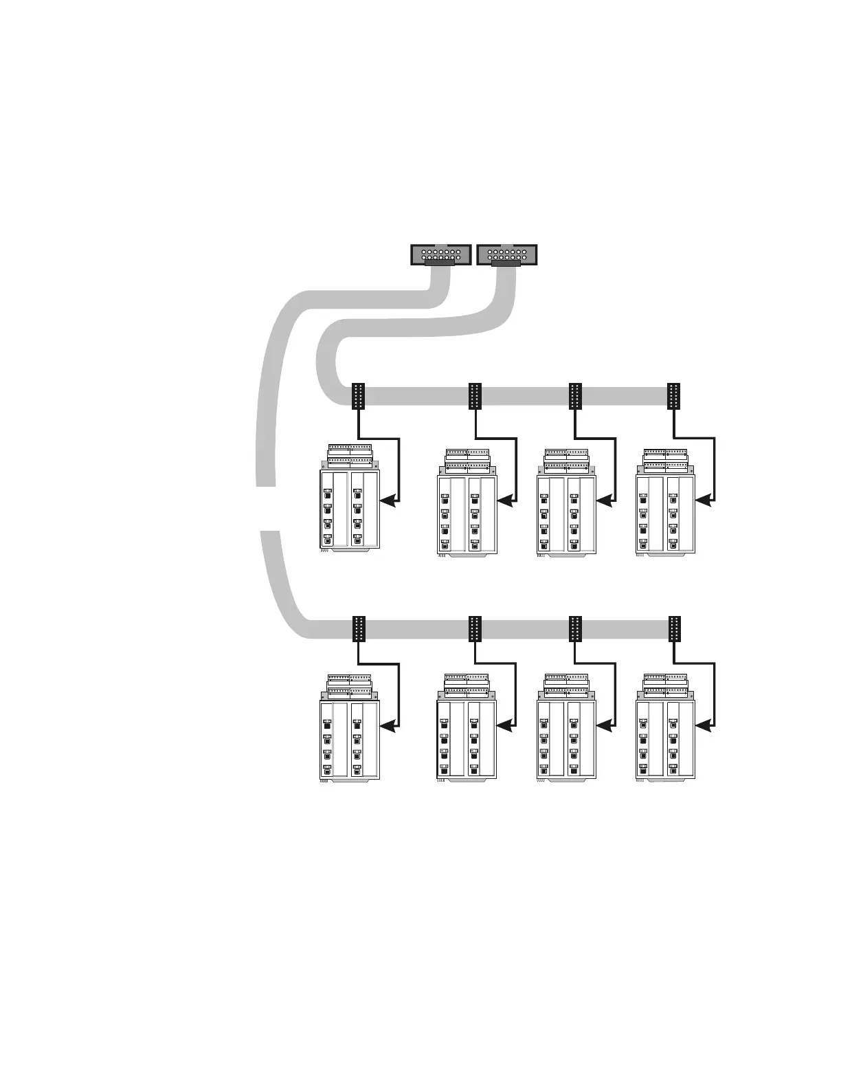
Expander Row Ribbon Cables connect panel circuit modules to the Control Panel.
Figure 22 shows a typical wiring setup using two Expander Row Ribbon Cables (P/N 71088) to
connect the control panel to two rows of four (4) panel circuit modules each below the Control
Panel in a CAB-4 Series backbox.
Figure 22 Expander Row Ribbon Cable Setup
3.7.4 Installing the Panel Circuit Modules
To install a panel circuit module such as a ICM-4RK or CRM-4RK into the chassis:
1. Angle the module into the chassis so that the lower board edge slips into the chassis slots as
shown in Figure 11.
2. Push the upper end of the module into the upper opening in the chassis.
3. Secure the module to the chassis with the two module screws (provided with the module).
Tighten securely.
4. Connect the Ribbon Cable to the module.
MODUL E
TYPE
LAMP S
SWITCH
MODUL E
TYPE
LAMP S
SWITCH
MODUL E
TYPE
LAMP S
SWITCH
MODUL E
TYPE
LAMP S
SWITCH
MODUL E
TYPE
LAMP S
SWITCH
MODUL E
TYPE
LAMP S
SWITCH
MOD UL E
TYPE
LAMP S
SWITCH
MODUL E
TYPE
LAMP S
SWITCH
MODUL E
TYPE
LAMP S
SWITCH
MODUL E
TYPE
LAMP S
SWITCH
MODUL E
TYPE
LAMP S
SWITCH
MODUL E
TYPE
LAMP S
SWITCH
MODUL E
TYPE
LAMP S
SWITCH
MODUL E
TYPE
LAMP S
SWITCH
MOD UL E
TYPE
LAMP S
SWITCH
MODUL E
TYPE
LAMP S
SWITCH
P1.1–P1.8 P2.1–P2.8 P3.1–P3.8 P4.1–P4.8
nfs640-icmribbon.cdr
Expander Row Ribbon Cable (P/N 71088)
Expander Row Ribbon Cable (P/N 71088)
Group of panel
modules in third
cabinet row
J5 - Second Row
P5.1–P5.8 P6.1–P6.8 P7.1–P7.8 P8.1–P8.8
J6 - Third Row
Group of panel
modules in second
cabinet row

 Loading...


