Operating manual X9 Series metering pumps
File: UT-4336 – Rev.0 Copyright © - OBL Metering pumps - All rights reserved Page 15
GB
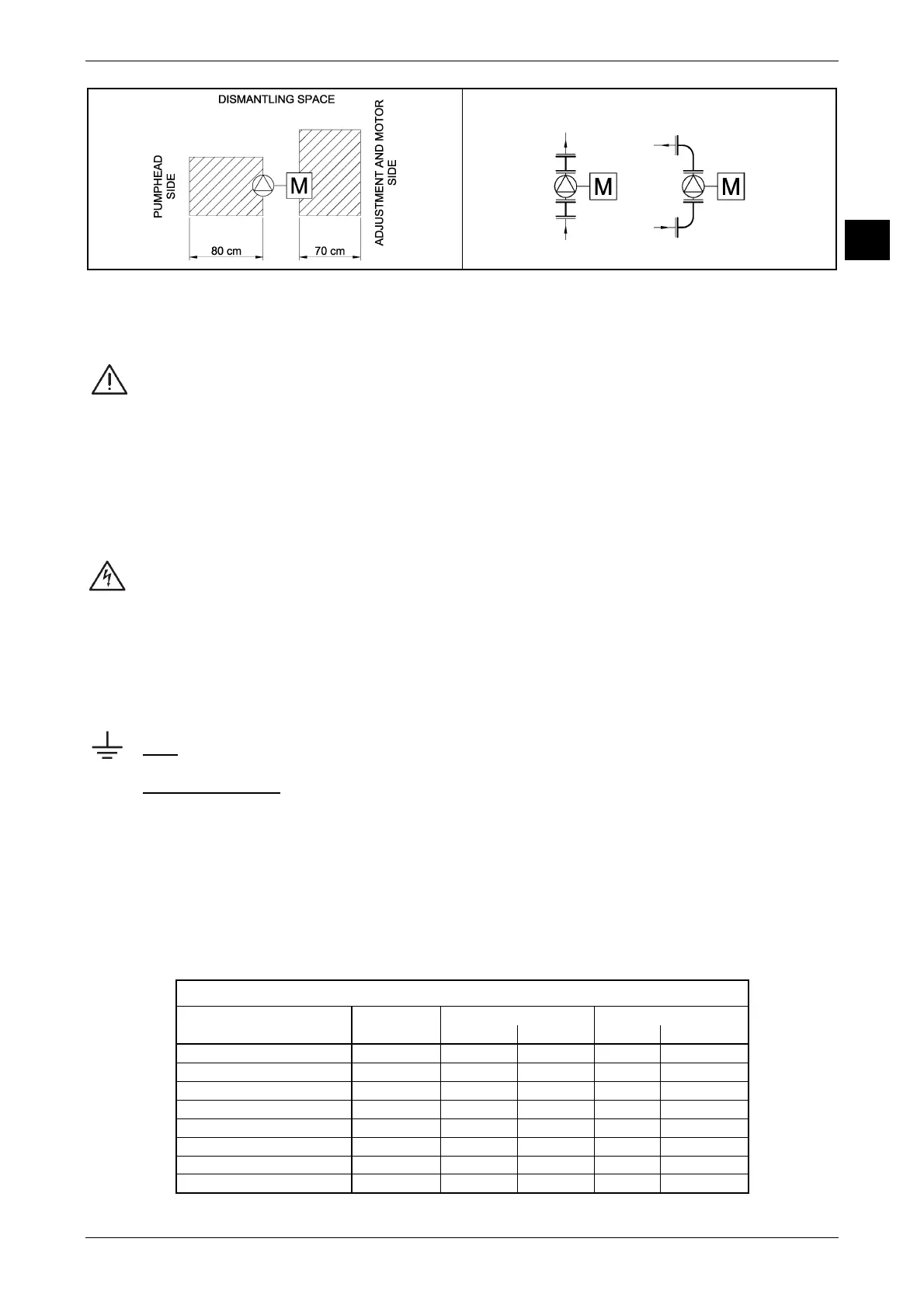
After the pump discharge connection we recommend the use of a cross connection, both to facilitate pump dismantling from the plant
and to allow (at a later time if necessary) the installation of a pressure gauge, safety valve, pulsation dampener.
Always verify complete sealing of fittings and pipe flanges, particularly on the suction side pipeline plant.
The entry of suctioned air prevents pump priming.
Before connecting the plant pipelines to the pump connections, it is absolutely necessary flush properly the
pipelines with water. Especially the suction pipeline and relevant feed tank. This preliminary flushing is often
underestimated by the installator and/or the end user; if this operation is not properly carried out, the pump will
become a collector of all foreing matters contained in the suction pipeline and tank, such as weld drops, gasket scraps,
soil and other stuff.
6.1.3
Connecting the motor to the mains
The metering pumps are always supplied with the use and maintenance instructions of the electric motor installed.
In addition, for ATEX pumps are also supplied the safety instructions, certification and ATEX conformity declaration.
Before carrying out electrical connections ensure that the mains supply voltage corresponds to that indicated
in the nameplate of the motor. Refer to the motor instructions manual and observe relevant provisions.
When for the mains cable connections in used a cable-gland, always choose it correctly according to the type of plant and properly for
the type of cable used.
The cable gland should be tightened so that the seal rings keep the necessary pressure:
- to prevent transmission of mechanical stress on the motor terminals
- to ensure mechanical protection (IP degree) of the terminal box
NOTE: Always make the ground connection using the appropriate terminal in the terminal box.
6.2 SUCTION PIPELINE
To ensure a proper and smooth operation of the pump it is essential design correctly the suction pipeline.
Especially when pump is installed higher than the liquid surface, above tank (good suction lift required), the factors to consider are:
- the internal diameter of the pipeline
- the overall length of the pipeline
- the arrangement or path of the pipeline
The internal diameter of the suction pipeline must be chosen according to the pump flow rate (see following table A).
Pump connections are sized/designed in excess to cover all applications.
Table A
Suction pipeline size according to maximum pump flow rate
Max. pump flow rate Quick Connections Flanged connections
(Qmax) fittings Threaded Glued UNI ANSI
Qmax < 15 l/h 4 x 6 mm - - - -
15 l/h < Qmax < 30 l/h 6 x 10 mm 1/4" - - -
30 l/h < Qmax < 125 l/h - 3/8" Ø 16 mm DN 10 1/2" ANSI
125 l/h < Qmax < 200 l/h - 1/2" Ø 20 mm DN 15 1/2" ANSI
200 l/h < Qmax < 300 l/h - 3/4" Ø 25 mm DN 20 3/4" ANSI
300 l/h < Qmax < 500 l/h - 1" Ø 32 mm DN 25 1" ANSI
500 l/h < Qmax < 2000 l/h - 1-1/2" Ø 40 mm DN 40 1-1/2" ANSI
Qmax > 2000 l/h - 2" Ø 50 mm DN 50 2" ANSI
Figure 3 Figure 4
 Loading...