Operating manual X9 Series metering pumps
File: UT-4336 – Rev.0 Copyright © - OBL Metering pumps - All rights reserved Page 21
GB
6.3.3
Pressure gauge
Always install a pressure gauge on the discharge pipeline, near the pump, and upstream of any other accessories that may cause
pressure increase (see previous figure 10). Allows to control plant conditions and check the pump actual working pressure.
ATTENTION: Knowing the pump actual working conditions in the plant can avoid equipment damage and,
especially, can prevent serious risk to persons or property present in the plant !
Consider the use of a pressure gauge also when dosing in a "free discharge / open flow" plant.
Doing so prevents accident caused by the following risks:
- freezing or solidification of fluid in the pipeline
- obstruction or accidentally squashing of the discharge pipeline (flexible pipes)
- variation of fluid viscosity in relation to the temperature
- when dosing the fluid through the injection nozzles
- other unforeseen risks that may cause quick, uncontrolled rise in pressure
The actual working pressure must NEVER exceed the maximum value indicated on the nameplate.
6.3.4
Calibration pot
Helps to detects the operating flow rate of the pump under actual working conditions and especially during normal operation, without
interrupting the dosing process.
Have to be installed on the suction pipeline, between the tank and the metering pump (see figure 11).
It is not a must accessory but, especially in process plants, it’s considered a complementary element to monitor the correct flow rate of
the pump.
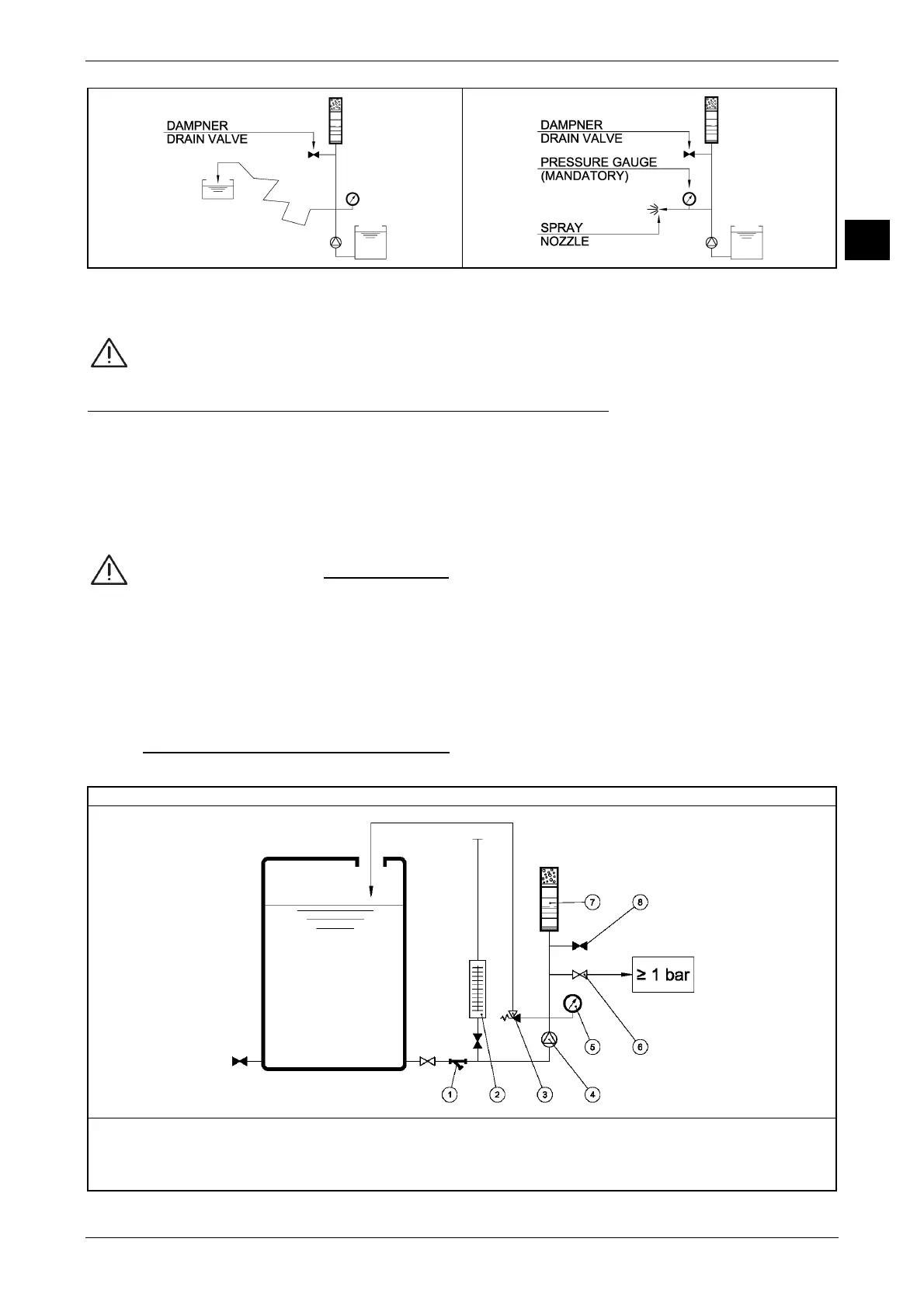
6.4 EXAMPLE OF PLANT FOR METERING PUMPS
All instructions for proper installation of metering pumps are grouped in figure 11.
Figure 11 EXAMPLE OF PLANT FOR METERING PUMPS
1 = "Y" filter 5 = Pressure gauge
2 = Calibration pot 6 = ON-OFF valve
3 = External safety valve 7 = Pulsation dampner
4 = Metering pump 8 = Pulsation dampner drain valve
Discharge pipeline long and winding
 Loading...