X9 Series metering pumps Operating manual
Page 18 Copyright © - OBL Metering pumps - All rights reserved File: UT-4336 – Rev.0
GB
The use of the filter should not affect the suction capacity of the pump. Carefully evaluate the real benefit of using the filter according
to the nature and characteristics of the handled fluid. If it is best to use it, properly choose the filter mesh size.
The pump can also convey solids in suspension (non soluble particles) but these are always considered as “disturbing source” elements
as they can cause:
- check valves obstruction
- accumulations and/or solidification inside the pumphead
- in case of diaphragm pumps, cutting or rupture of it
As a general rule, we do not recommend filter installation in the following case:
- viscous liquid (e.g. polyelectrolyte)
- liquid that coagulates, solidifies or crystallize easily (e.g. caustic soda, ferric chloride)
ATTENTION: A small size filter may impede the suction inlet flow, clogging up the pipeline. Use Y filters (a.k.a.
Y strainers) with sizes larger than the diameter of pumps suction side connection.
The filter mesh size and characteristics are linked to the nature of the handled fluid and the pump flow rate. For liquids having viscosity
not exceeding 200 cps see the table below.
Max. pump flow rate
(Qmax)
Filter mesh
(US standard)
Mesh opening
(mm)
Qmax < 15 l/h 100 0,152
15 l/h < Qmax < 50 l/h 60 0,251
50 l/h < Qmax < 100 l/h 50 0,353
100 l/h < Qmax < 300 l/h 40 0,422
300 l/h < Qmax < 1000 l/h 30 0,599
Qmax > 1000 l/h 30 0,599
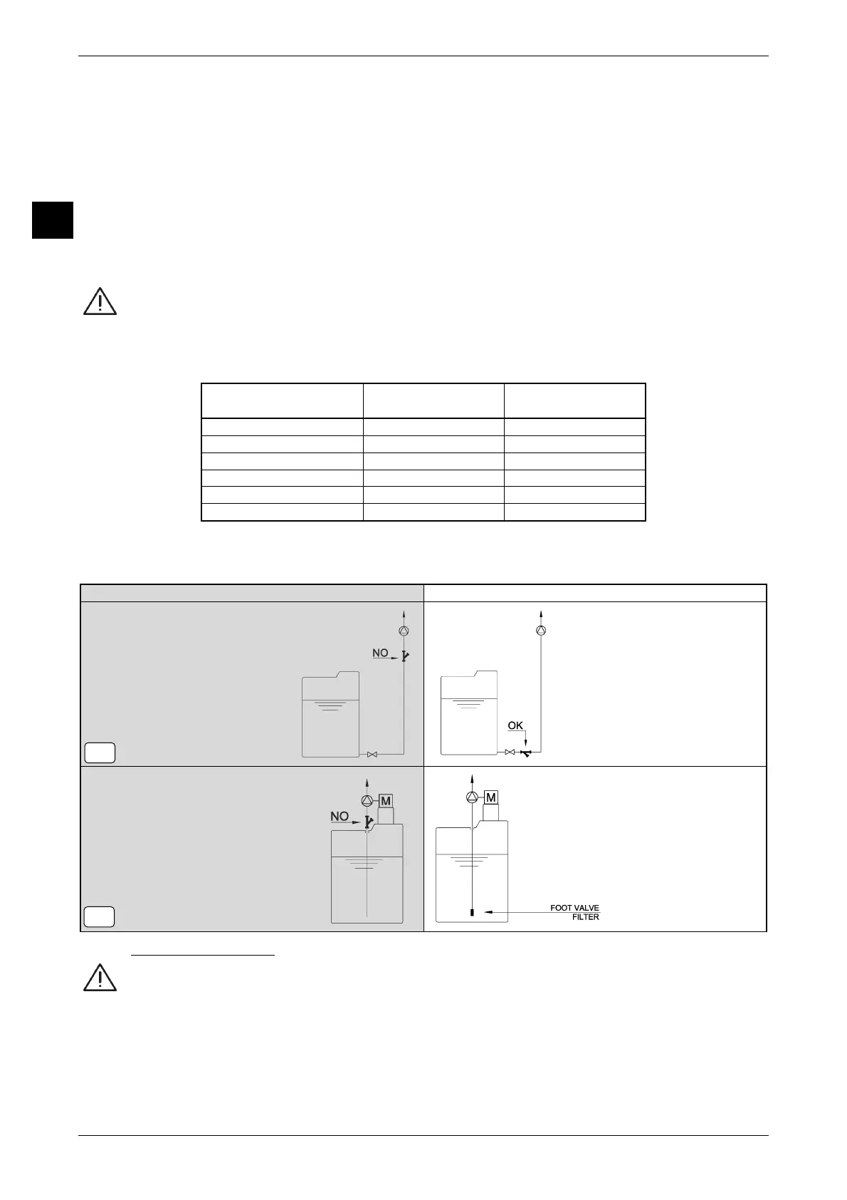
To avoid suctioning of impurities, especially in dosing liquids with suspensions, do not suction from the bottom of the tank but lift the
suction point 10 cm from the bottom (see previous figure 5-A).
Figure 7 shows some examples of filter installation in suction pipeline.
Figure 7 INCORRECT INSTALLATION CORRECT INSTALLATION
6.3 DISCHARGE PIPELINE
Avoid to build the discharge pipeline, or worse to install equipment, directly above the pump.
If the handled fluid free surface of the suction tank is higher than the delivery reservoir this may trigger the siphoning phenomenon
(see Figure 8). The fluid moves in a spontaneous and uncontrolled manner from the suction tank to the discharge tank, going
through the pump without it being able to control the flow rate in any way.
To avoid and prevent this phenomenon we suggest to install on discharge pipeline a backpressure valve, or else raise the pipeline so to
break the fluid vein. Discharge pressure must be greater than suction pressure by at least 0,3 bar (0,5 bar for small flow rates).
See indications shown in figure 8 for discharge pipeline arrangements.
7-A
7-B
 Loading...