4-47
4 Installation and Wiring
NJ-series CPU Unit Hardware User’s Manual (W500)
4-4 Wiring
4
4-4-8 Wiring B7A Interface Units
Precautions for Correct UsePrecautions for Correct Use
• Confirm that terminals are connected correctly. If connections are incorrect, the internal com-
ponents of the B7A Interface Unit and B7A Link Terminal may be damaged.
• Route the signal lines in separate ducts both inside and outside the control panel to isolate
them from power lines.
• Connect cables at a distance that is within the range given in the specifications.
• Always turn OFF the power to the CPU Unit and all other Units before connecting the commu-
nications cables.
• Always lay communications cables within ducts.
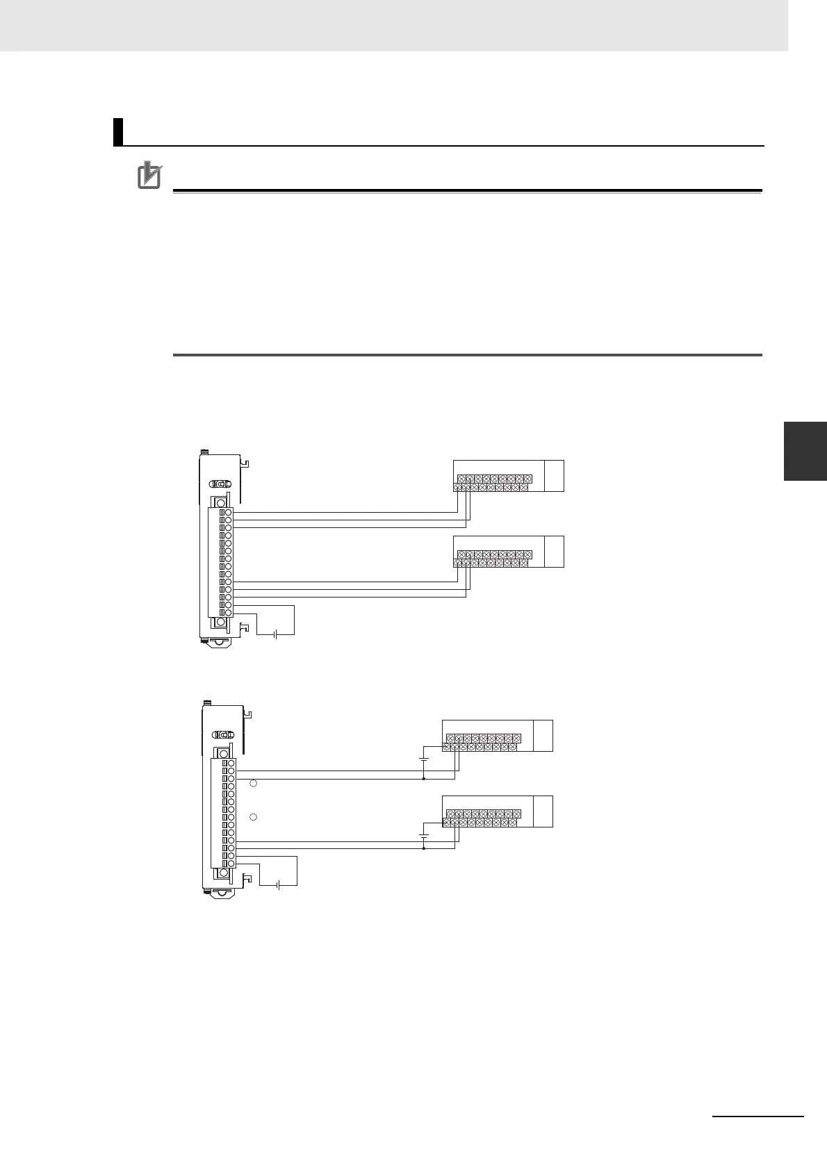
Standard Mode
• Power Supply on One Side (Common Power Supply)
• Power Supply on Both Sides (Separate Power Supplies)
Connection Diagrams
V1
SIG1
G1
V2
SIG2
G2
V3
SIG3
G3
V4
SIG4
G4
V
G
+
−
B7A Interface Unit
12 to 24 V DC
Transmission distance: 100 m max.
Transmission cable: VCTF 0.75mm
2
min.
B7A Link Terminal
B7A Link Terminal
V1
SIG1
G1
V2
SIG2
G2
V3
SIG3
G3
V4
SIG4
G4
V
G
−
SIG
−
+
+
+
−
B7A Interface Unit
12 to 24 V DC
Transmission cable: VCTF 0.75mm
2
min.
B7A Link Terminal
B7A Link Terminal
12 to 24 V DC
Transmission distance:
500 m max.
12 to 24 V DC
 Loading...