Appendices
A-98
NJ-series CPU Unit Hardware User’s Manual (W500)
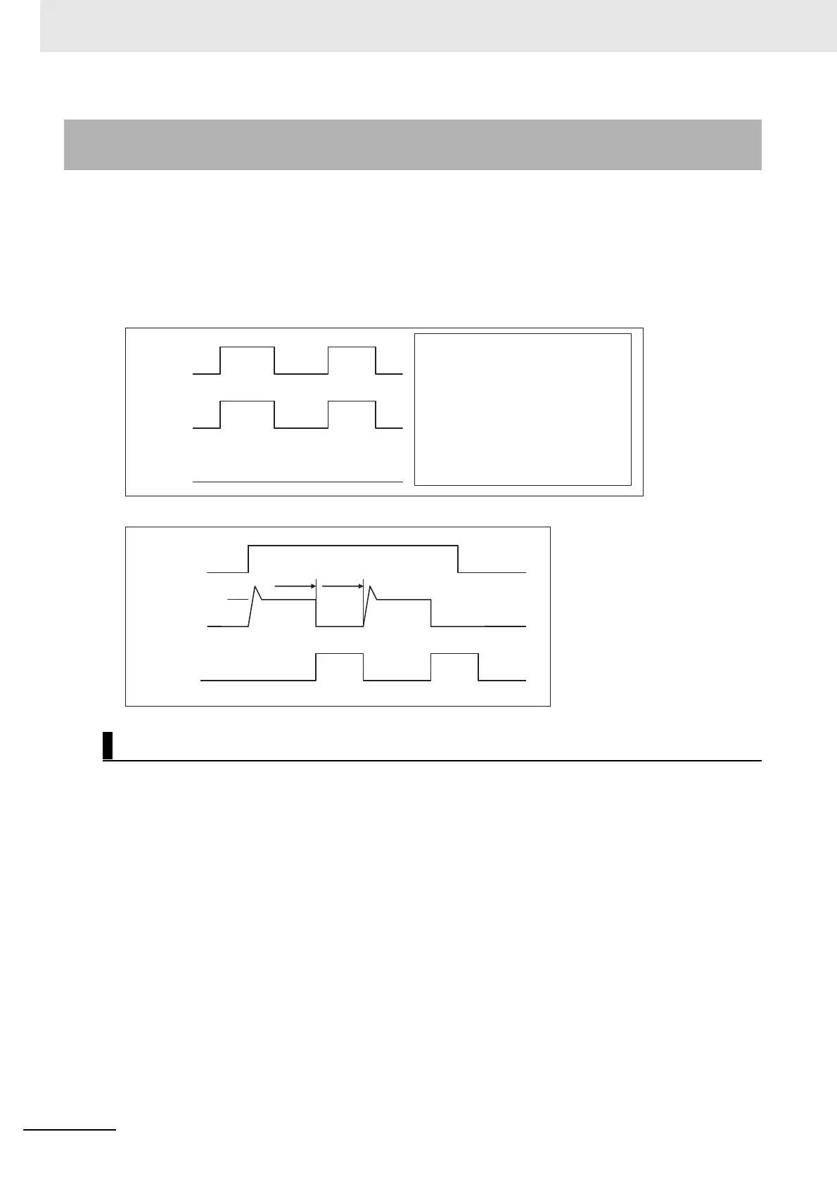
As shown below, normally when the output bit turns ON (OUT), the transistor will turn ON and then out-
put current (Iout) will flow. If the output current (Iout) exceeds the detection current (Ilim) when an over-
load or short-circuit occurs, the output current (Iout) will be limited as shown in Figure 2. When the
junction temperature (Tj) of the output transistor reaches the thermal shutdown temperature (Tstd), the
output will turn OFF to protect the transistor from being damaged, and the alarm output bit will turn ON
to light the ERR indicator. When the junction temperature (Tj) of the transistor drops down to the reset
temperature (Tr), the ERR indicator will be automatically reset and the output current will start flowing.
Figure 1 Normal Operation
Figure 2 Operation for Overload or Short Circuit
Although these Units are provided with load short-circuit protection, these are for protecting internal cir-
cuits against momentary short-circuiting in the load. As shown in Figure 2, the load short-circuit protec-
tion is automatically released when the Tj equals to Tr. Therefore, unless the cause of short-circuit is
removed, ON/OFF operations will be repeated in the output. Leaving short-circuits for any length of
time will cause internal temperature rise, deterioration of elements, discoloration of the case or PCBs,
etc. Therefore, observe the following restrictions.
A-4-2 Load Short-circuit Protection for CJ1W-
OD204/OD212/OD232/MD232
Operating Restrictions for the CJ1W-OD204/OD212/OD232/MD232
OUT
ON
OFF
I
OUT
ON
OFF
ERR
ON
OFF
OUT: Output bit
I
OUT
: Output current
ERR: Alarm output, ERR indicator
I
lim
: Detection current
Tj: Junction temperature of transistor
Tstd: Thermal shutdown temperature
Tr: Reset temperature
OUT
ON
OFF
I
OUT
ON
OFF
ERR
ON
OFF
I
lim
Tj =Tstd Tj =Tr
 Loading...