8 Pulse Output Units
8 - 32
NX-series Position Interface Units User’s Manual (W524)
This section describes the data configuration for each of the 11 data items for I/O allocation.
Refer to Controlword on page 8-35 for information on the Controlword.
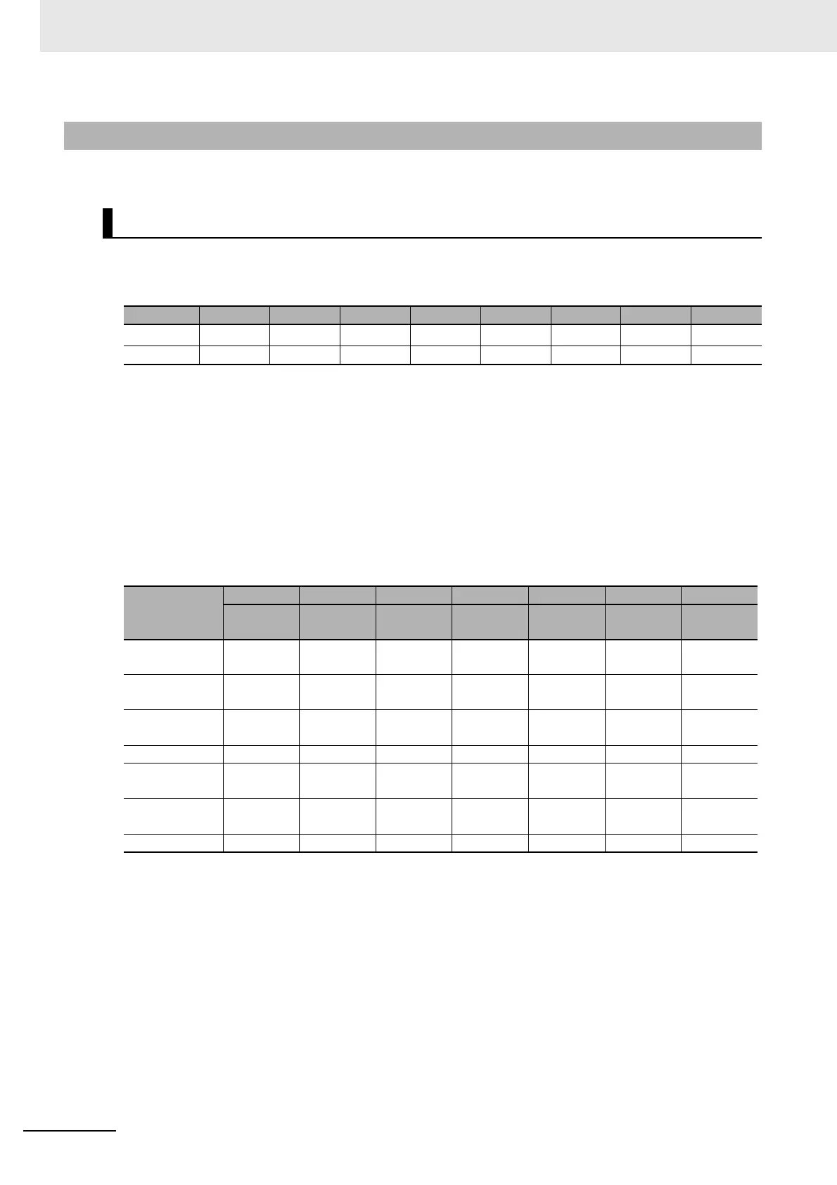
The bit configuration of the Statusword is given in the following table.
Statusword Status Indications
The status is indicated by the combination of the bits in the Statusword, as shown in the following table.
8-8-2 Data Details
Statusword
Byte Bit 7 Bit 6 Bit 5 Bit 4 Bit 3 Bit 2 Bit 1 Bit 0
0---
sod
*1
*1. “sod” is an abbreviation for Switch ON Disabled.
qs
*2
*2. “qs” is an abbreviation for Quick Stop Done.
ve
*3
*3. “ve” is an abbreviation for Voltage Enabled.
f
*4
*4. “f” is an abbreviation for Fault.
oe
*5
*5. “oe” is an abbreviation for Operation Enabled.
so
*6
*6. “so” is an abbreviation for Switched ON.
rtso
*7
*7. “rtso” is an abbreviation for Ready to Switch ON.
+1 --- --- --- --- --- --- --- ---
State
Bit 6 Bit 5 Bit 4 Bit 3 Bit 2 Bit 1 Bit 0
Switch ON
Disabled
Quick
Stop Done
Voltage
Enabled
Fault
Operation
Enabled
Switched
ON
Ready to
Switch ON
Not Ready to
Switch ON
00
*1
*1. This signal monitors the ON/OFF status of the main power supply circuit, but this signal is always ON for the
Pulse Output Unit.
0000
Switch ON Dis-
abled
11
*1
0000
Ready to
Switch ON
01
*1
0001
Switched ON 0 1
*1
0011
Operation
Enabled
01
*1
0111
Fault Reaction
Active
01
*1
1111
Fault 0 1
*1
1000
 Loading...


