9 - 3
9 Application Example
NX-series Position Interface Units User’s Manual (W524)
9-2 Configuration Example
9
9-2-1 System Configuration
9-2 Configuration Example
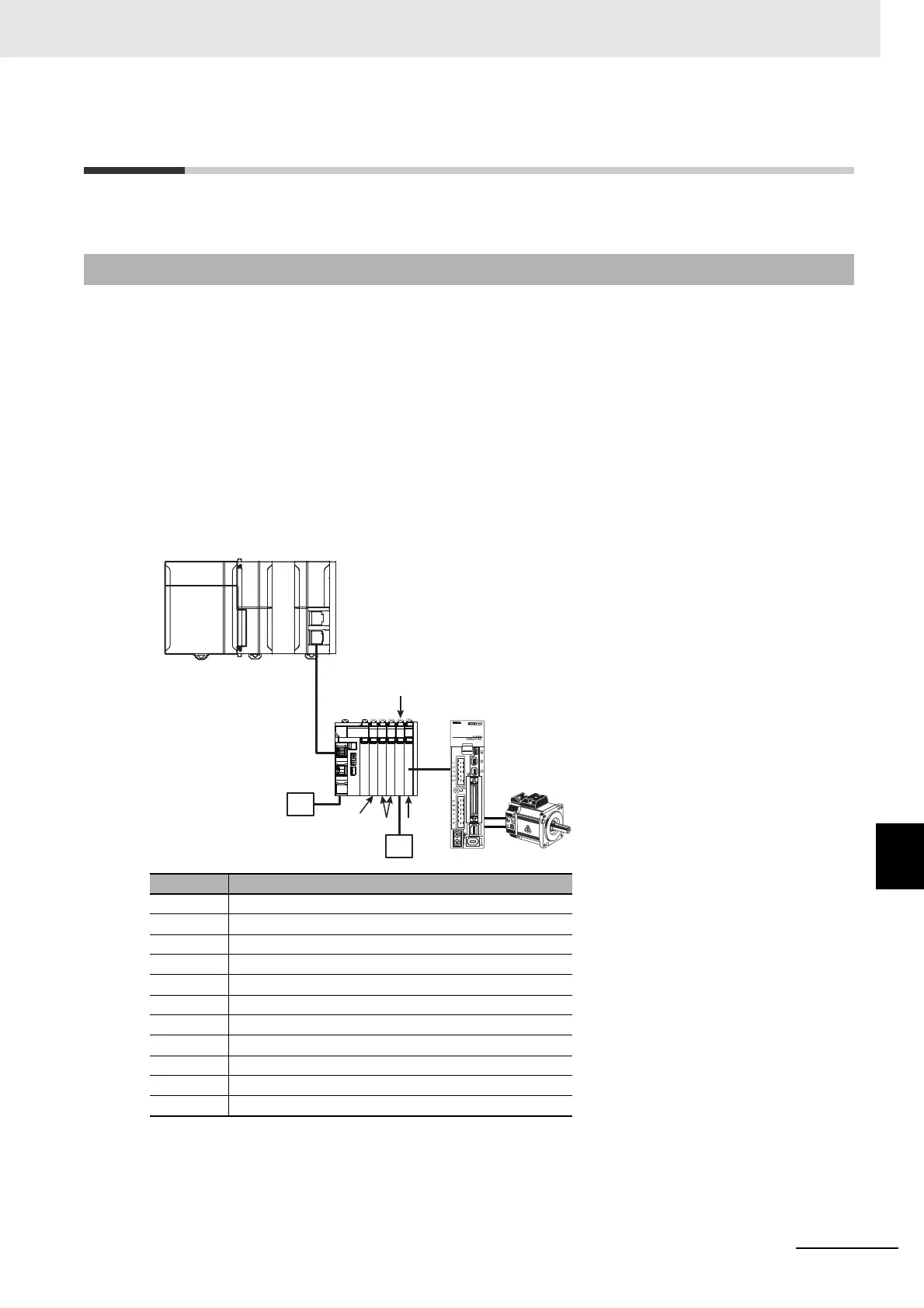
This section describes the system configuration and provides a wiring example to the Servo Drive.
This section describes the example system configuration to implement the control described in the pre-
vious section with an NJ-series Controller, EtherCAT Coupler Unit, and Position Interface Units.
To construct a motor control system with a Pulse Output Unit, Digital Input Units are required to use
external sensors, such as for limit sensor inputs and error inputs.
A Digital Output Unit is used for a RUN output and an error reset output.
The Digital I/O Units are connected after the EtherCAT Coupler Unit in the same way as the Pulse Out-
put Unit.
The following diagram shows the example Unit configuration for the Controller.
9-2-1 System Configuration
Symbol Description
(A) Power Supply Unit
(B) NJ-series CPU Unit
(C) EtherCAT Coupler Unit
(D) Additional I/O Power Supply Unit
(E) Servo Drive with a pulse string input
(F) Servomotor
(G) Pulse Output Unit
(H) I/O power supply
(I) Digital Input Units
(J) Digital Output Unit
(K) Unit power supply and I/O power supply
(C)
(E)
(B)(A)
(G)
(K)
(I)
(J)
(H)
(D)
(F)
 Loading...


