Chapter 3
3-21
System Design and Installation
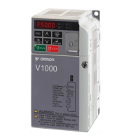
• Separate power supply cables and signal cables when wiring.
■ Selecting Components
This section explains the criteria for selecting the connection components required for
improving noise resistance. These criteria include capacity performance, applicable
range, and so on. For more details, contact the manufacturers directly.
● No-fuse Breakers (NFB)
When selecting no-fuse breakers, take into consideration the maximum output current and the inrush
current.
Maximum input current:
The momentary maximum output for a Servo Driver is approximately three times that of the rated
output, and a maximum output of three seconds can be executed. Therefore, select no-fuse breakers
with an operating time of at least five seconds at 300% of the rated maximum output. General-pur-
pose and low-speed no-fuse breakers are generally suitable. The table in 3-2-3 Terminal Block Wir-
ing shows the rated power supply input currents for each Servomotor. Select a no-fuse-breaker with
a rated current greater than the total effective load current (when multiple Servomotors are used).
When making the selection, add in the current consumption of other controllers, and so on.
Servo Driver inrush current:
With low-speed no-fuse breakers, an inrush current 10 times the rated current flows for 0.02 sec-
onds. For a simultaneous inrush for multiple Servo Drivers, select a no-fuse-breaker with a 20-ms
allowable current greater than the total inrush current shown in the following table for the applicable
Servomotor models.
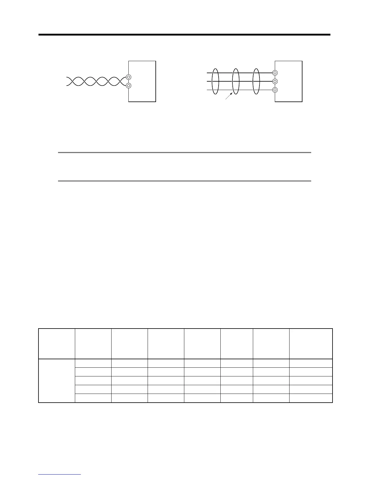
Smart
Servo
Driver
Power
supply
voltage
V
Servo
Driver
model
(R7D-)
Capacity Rated
current
A (rms)
Inrush
current
circuit
A (0-p)
125% of
rated
current
NFB model
Single-
phase
100 APA3L 30 W 1.64 90 2.05 NF30-SW 10A
100 APA5L 50 W 2.2 90 2.75 NF30-SW 10A
100 AP01L 100 W 4 90 5 NF30-SW 10A
100 AP02L 200 W 6.8 90 8.5 NF30-SW 10A
100 AP04L 400 W 11 90 13.75 NF30-SW 15A
Driver
Binding
or
Driver
Correct: Properly twisted
Correct: Cables are bound.
L1C
L1
L2
L3
L2C
 Loading...