Chapter 4
4-26
Operation
4-7 Operating Functions
4-7-1 Position Control
■ Functions
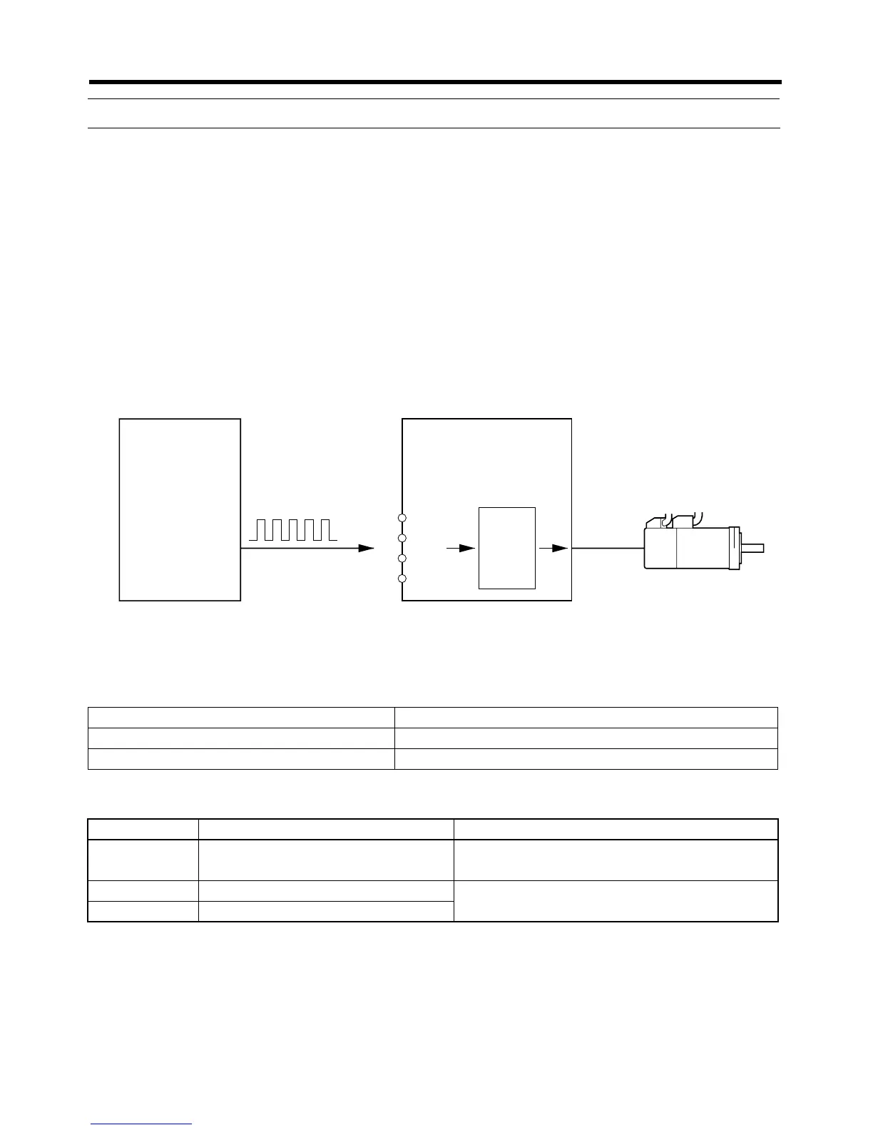
• Perform position control using the pulse train input from CN1-1,2 for CW and CN1-3,4 for CCW.
• The Servomotor rotates using the value of the pulse train input multiplied by the electronic gear
ratio (Pn202, Pn203).
Note If function switch 6 is OFF to enable the function switch settings, this parameter is ignored and
the setting on function switches 4 and 5 (resolution setting) is used.
■ Settings
● Using Function Switches (Function Switch 6 Turned OFF)
● Using Parameters (Function Switch 6 Turned ON)
Function switch Explanation
Command pulse input setting (switch 3) Set to match the Controller command pulse type.
Resolution setting (switches 4 and 5) Set to 500, 1,000, 5,000, or 10,000.
Parameter No. Parameter name Explanation
Pn200.0 Position control setting 1
Command pulse mode
Set to match the controller command pulse status.
Pn202 Electronic gear ratio G1 (numerator) Set the pulse routes for the command pulse and
Servomotor travel amount. 0.01
≤ G1/G2 ≤ 100
Pn203 Electronic gear ratio G2 (denominator)
Controller with pulse train output
Position Control Unit
Pulse train
SMARTSTEP A-series Servo Driver
Position Control Mode
Electronic gear ratio
(Pn202, Pn203)
G1/G2
SMARTSTEP A-series
Servomotor
+CW
−CW
+CCW
−CCW
1
2
3
4
 Loading...