6
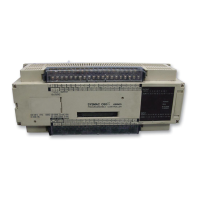
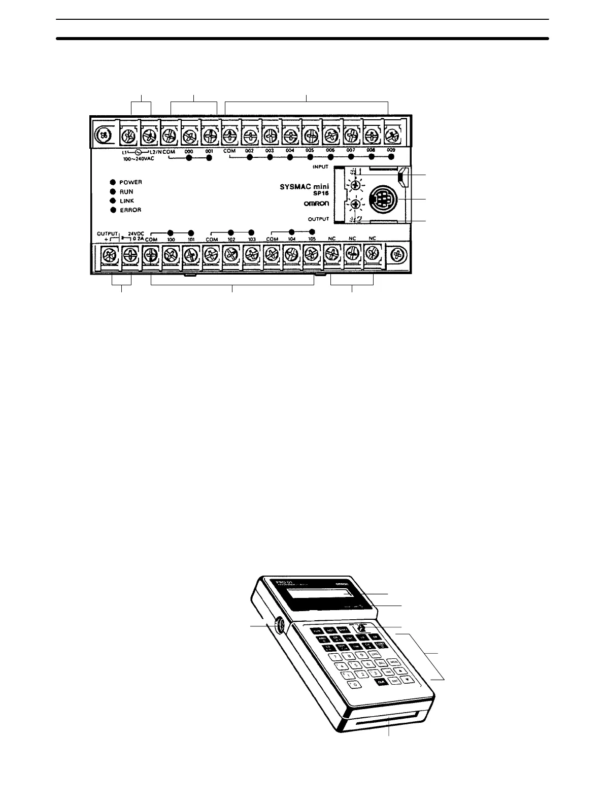
SP16 and SP20 The SP20 is essentially the same as the SP16. The SP16 is shown below.
RDM(23) input
(See note 3)
Inputs
Analog timer 1
setting adjustment
Programming Console/
Link Adapter connector
Power terminals
for external supply
24 VDC, 0.2 A (see note 1)
Outputs NC
Analog timer 2
setting adjustment
Power supply
Note 1. The power terminals for external supply are provided for the 100 to 240
VAC model (SP__-__-A) only.
2. Connect nothing to the NC terminal.
3. Input 000 is the counter input and 001 is the hard reset input for the RE-
VERSIBLE DRUM COUNTER, RDM(23). When RDM(23) isn’t being
used, these terminals can be used as normal input points but the input
signal must be below 1 kHz.
Indicators The PC has four indicators on the front panel, POWER, RUN, LINK, and ER-
ROR. The functions of the indicators are presented as follows.
POWER (green): Lit while power is supplied.
RUN (green): Lit when the PC is in RUN mode and operating normally.
LINK(green): Lit when the PC Link is operating normally.
ERROR(red): Lights when self-diagnosis detects an error. The PC will
stop operating.
1-3-2 Programming Console
The Programming Console is shown below.
Connecting
cable connector
Display
Memory card access indicator
Mode switch
Memory card slot
Key pad
Units Section 1-3
 Loading...