EN-20
7. Monitors
The V7 allows you to monitor various conditions, such as output current and status of
multi-function inputs. These monitors are indicated by "U-".
*1 The status indicator LED is not turned ON.
*2 When in the vector control mode,”---“ will be displayed.
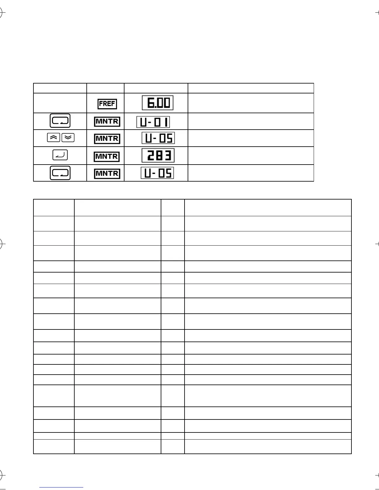
Key sequence Indicator Display example Explanation
Power ON
Press the Mode Key repeatedly until the PRGM
indicator is lit.
Use the Increment or Decrement Key to set the
monitor number.
Press the Enter Key.
The data of the selected monitor number will be
displayed.
Press the Enter or Mode Key.
The monitor number will be displayed.
Constant
No.
Name Unit Description
U-01 Frequency reference
(FREF)*1
Hz Frequency reference can be monitored.
(same as FREF)
U-02 Output frequency
(FOUT)*1
Hz Output frequency can be monitored.
(Same as FOUT)
U-03 Output current
(IOUT)*1
A Output current can be monitored.
(Same as IOUT)
U-04 Output voltage V Output voltage can be monitored.
U-05 DC voltage V Main circuit DC voltage can be monitored
U-06 Input terminal status - Input terminal status of control circuit terminals can be
monitored.
U-07 Output terminal status - Output terminal status of control circuit terminals can be
monitored.
U-08 Torque monitor % The amount of output torque can be monitored. When V/f
control mode is selected, “----“ is displayed.
U-09 Fault history (last 4 faults) - Last four fault history is displayed.
U-10 Software No. - Software No. can be checked.
U-11 Output power*2 KW Output power can be checked.
U-12 Frequency offset monitor Hz Frequency offset can be monitored.
U-14 ASCII code from the PLC - ASCII code from the PLC is displayed.
U-15 Data reception error - Contents of MEMOBUS communication data reception
error can be checked.
(contents of transmission register No. 003DH are the same)
U-16 PID Feedback % Input 100(%) Max. output frequency or equivalen.
U-17 PID input % ±100(%). Where Max. output frequency=100%
U-18 PID output % ±100(%). Where Max. output frequency=100%
U-19 Frequency reference bias
monitor
% ±100(%). Where Max. output frequency=100%
I43-EN-01+V7+Quick_Guide.book Seite 20 Dienstag, 25. April 2006 8:56 08
 Loading...


